Injection mold and method for molding an optical element

A technology for injection molding and optical components, which is applied in optical components, household appliances, and other household appliances, etc. It can solve the problems of fine shape replication, severe heat dissipation of molten resin, etc., and achieve reduced heat dissipation, good heat preservation, and high replicability Improved effect

Inactive Publication Date: 2006-01-04
KONICA MINOLTA OPTO
View PDF1 Cites 6 Cited by
  • Summary
  • Abstract
  • Description
  • Claims
  • Application Information

AI Technical Summary

Problems solved by technology

However, a problem has been found that the mold base material 51 with relatively high thermal conductivity is exposed in the cavity portion 51a adjacent to the fla

Method used


Image

  • Injection mold and method for molding an optical element
  • Injection mold and method for molding an optical element
  • Injection mold and method for molding an optical element

Examples


Embodiment 1

[0019] (Example 1, refer to figure 1 )

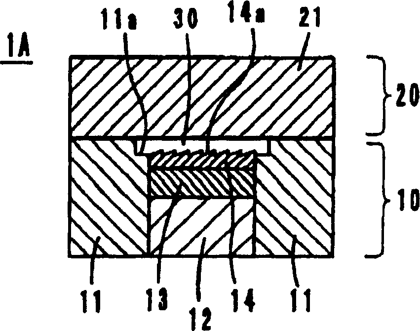
[0020] The mold 1A of embodiment 1 is as figure 1 As shown, it consists of a movable mold 10 and a fixed mold 2. The movable mold 10 is composed of base materials 11 and 12 , a heat insulating layer 13 and a surface processing layer 14 . The fixed mold 20 is composed of a base material 21 .

[0021] The surface processing layer 14 is finished according to the optical surface shape of molded products (optical elements) such as lenses, reflectors, prism plates, and light guide plates, and forms fine shapes 14a such as diffraction gratings, prism surfaces, and flashing surfaces. The cavity 30 is constituted by the surface-processed layer 14 , the base material 21 , and the inner peripheral upper edge of the base material 11 .

[0022] The base metals 12 and 21 are made of common mold base materials, such as metal materials such as carbon steel or stainless steel. The thermal conductivity of carbon steel is 50W / m·K, and the thermal c...

Embodiment 2

[0028] (Example 2, refer to figure 2 )

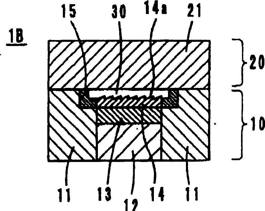
[0029] The mold 1B of embodiment 2 is as figure 2 As shown, the ring-shaped heat insulating material layer 15 is positioned on the upper edge of the inner periphery of the base material 11 constituting the movable mold 10, that is, a portion constituting a part of the cavity 30, in other words, between the base material 11 and the surface-processed layer 14. between.

[0030] In this mold 1B, the base material 11 is made of a common mold base material. The heat insulating material layer 15 is formed of various stainless steels, titanium alloys, and nickel alloys shown in Example 1 that have low thermal conductivity. Or it can also be used as silicon nitride (Si 3 N 4 , 20W / m·K) or aluminum titanate (Al 2 o 3 ·TiO 2 , 1.2W / m·K) and so on. It can also be formed with a heat-resistant polymer such as polyimide resin (thermal conductivity: 0.28 W / m·K). Of course, materials other than those mentioned above can also be used, and ce...

Embodiment 3

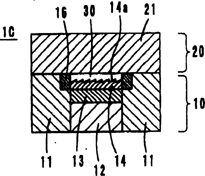
[0033] (Example 3, refer to image 3 )

[0034] The mold 1C of embodiment 3 is as image 3 As shown, a heat-insulating material layer 16 is provided instead of the heat-insulating material layer 15 in the mold 1B of Embodiment 2 described above. The material of the heat insulating material layer 16 is the same as that of the heat insulating material layer 15, and the other configurations and materials are the same as those of the second embodiment. Therefore, its function and effect are also the same as in Example 2.


PUM

PropertyMeasurementUnit
Thermal conductivityaaaaaaaaaa

Abstract

An injection mold composed of a movable mold and a fixed mold. The movable mold has bases, a heat insulating layer and a surface processed layer, and the fixed mold has a base. A heat insulator is provided on the inner circumferential surface of the base of the movable mold at a part forming a wall of a cavity. The heat insulating layer is in the rear of the surface processed layer, and therefore, the transfer accuracy of a fine configuration of the surface processed layer is improved. Additionally, since the heat insulator is provided adjacent to the fine configuration, heat radiation from resin is inhibited, and the transfer accuracy of the fine configuration is further improved.

Description

technical field [0001] The present invention relates to a mold for injection molding and a method for molding optical elements, and more particularly to a mold for injection molding and a method for molding small and light optical elements such as lenses and light guide plates. Background technique [0002] In recent years, due to the development of resin materials and injection molding technology, various small and lightweight lenses, prism plates, light guide plates, etc. have been developed, and the demand for optical components such as optical sensor devices and mobile phones is increasing. For such optical elements, molds for injection molding are required to reproduce fine shapes for diffraction with high precision, fine shapes such as prism surfaces and shiny surfaces, or smooth surfaces. [0003] Conventionally, in order to achieve high-precision reproducibility, Japanese Patent Application Laid-Open No. 2002-96335 proposes an injection molding die 50 such as Figure...

Claims


Application Information

Patent Timeline
IPC IPC(8): B29C45/26B29C45/73B29L11/00B29C33/02B29D11/00
CPCB29D11/00B29D11/00432B29C45/73B29C2033/023B29C33/02
Inventor 奥村佳弘内藤笃関原幹司
Owner KONICA MINOLTA OPTO
Why Eureka
Try Eureka