Micro oxygen pump based on hydrogen peroxide solution decomposition

A technology of hydrogen peroxide and oxygen, which is applied in the direction of oxygen preparation, microstructure devices without moving elements, filtration and separation, etc., can solve the problems of weak driving ability and driving pressure, and achieve strong continuous driving ability, simple structure, and low energy consumption for opening low effect

Inactive Publication Date: 2006-01-04
SHANGHAI JIAO TONG UNIV
View PDF0 Cites 3 Cited by
  • Summary
  • Abstract
  • Description
  • Claims
  • Application Information

AI Technical Summary

Problems solved by technology

It has the characteristics of novel principle, simple structure and low manufacturing cost, and overcomes the disadvantages of weak driving ability and too small driving pressure of the heat pump

Method used


Image

  • Micro oxygen pump based on hydrogen peroxide solution decomposition

Examples


Embodiment Construction

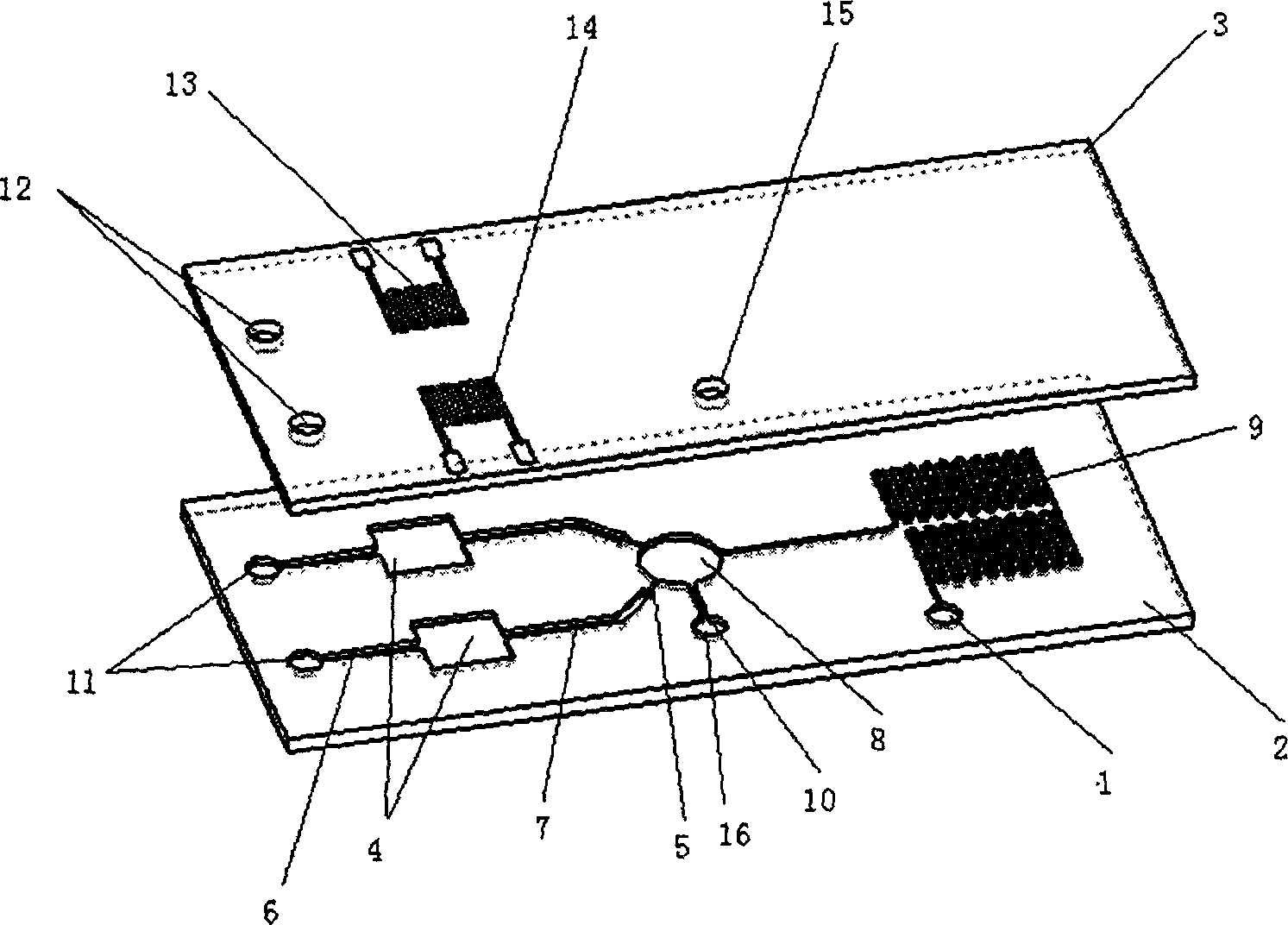
[0018] Such as figure 1 As shown, the present invention is composed of two layers, which are respectively the silicone rubber substrate 2 including the pump cavity structure and microchannels and the glass substrate 3 including the heating electrode and the sensing electrode, and the glass substrate 3 is encapsulated by ultraviolet light irradiation. Arranged above the silicone rubber base 2, the silicone rubber base 2 is provided with parallel hydrogen peroxide pump chambers 4, and hydrogen peroxide inlet microchannels 6 and oxygen outlet microchannels 7 are respectively arranged at opposite positions on both sides of the hydrogen peroxide pump chamber 4, The hydrogen peroxide inlet microchannel 6 is connected to the hydrogen peroxide inlet 11, the end of the oxygen outlet microchannel 7 is connected to the capillary microvalve 5, and the other side of the capillary microvalve 5 is connected to the liquid storage chamber 8, and the lower side of the liquid storage chamber 8 is...


PUM


Abstract

The micro oxygen pump based on the decomposition of hydrogen peroxide solution consists of silicone rubber substrate and glass substrate. Inside the silicone rubber substrate, there are parallel hydrogen peroxide solution pump cavities. On two sides of the hydrogen peroxide solution pump cavities, there are hydrogen peroxide solution inlet micro passage communicated with the hydrogen peroxide solution inlet and oxygen outlet micro passage with end connected to capillary micro valve with the other side communicated with the liquid storage cavity. There are also sample inlet micro passage below the liquid storage cavity and snaky micro passage connected to the liquid outlet. On the glass substrate, there are drive electrodes comprising micro heating electrodes set over the hydrogen peroxide solution pump cavities and micro sensing electrodes set inside the hydrogen peroxide solution pump cavities. The present invention has low power consumption and high continuous drive capacity, and can generate relatively high pressure.

Description

technical field [0001] The invention relates to a gas-liquid micro pump, in particular to a micro oxygen pump based on hydrogen peroxide decomposition. Used in the field of microelectromechanical systems. Background technique [0002] Micropumps are the core components to realize microfluidic control. Micropumps based on MEMS processing technology can generally be divided into two types according to the principle of the pump: mechanical and non-mechanical. According to the type of actuation, mechanical pumps can be divided into: piezoelectric, pneumatic, thermopneumatic, electrostatic and electromagnetic, etc. The working principle of these pumps is basically to use a relatively high voltage to actuate a membrane, which produces a reciprocating motion to drive the liquid along the microchannel. The advantage of the mechanical pump is that it can be applied to any liquid, and the flow rate is less affected by the properties of the liquid flow in the channel and the properti...

Claims


Application Information

Patent Timeline
Patent Type & Authority Applications(China)
IPC IPC(8): B81B1/00C01B13/02
Inventor 陈文元牛志强邵诗逸张卫平
Owner SHANGHAI JIAO TONG UNIV
Why Eureka
Try Eureka