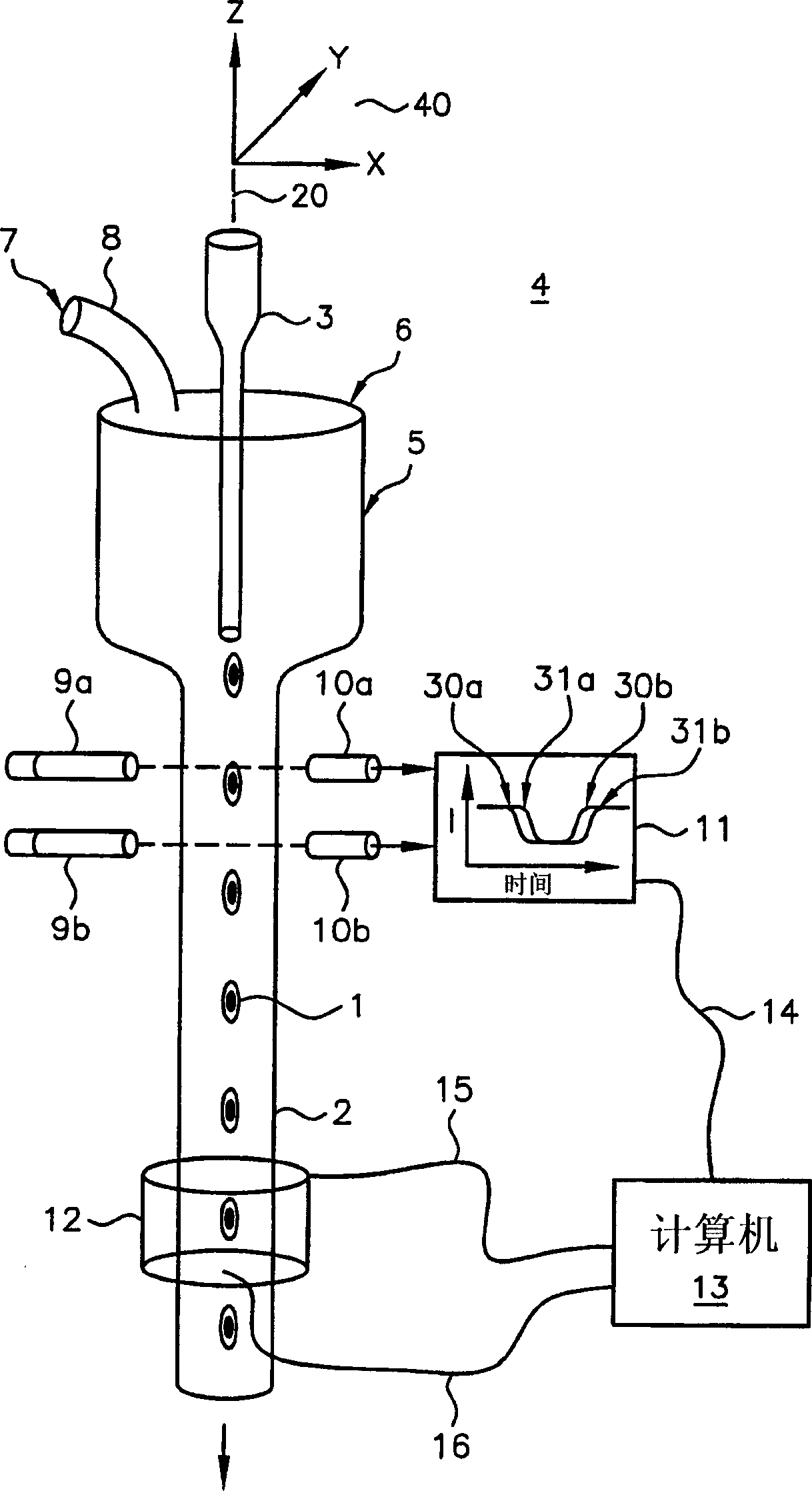
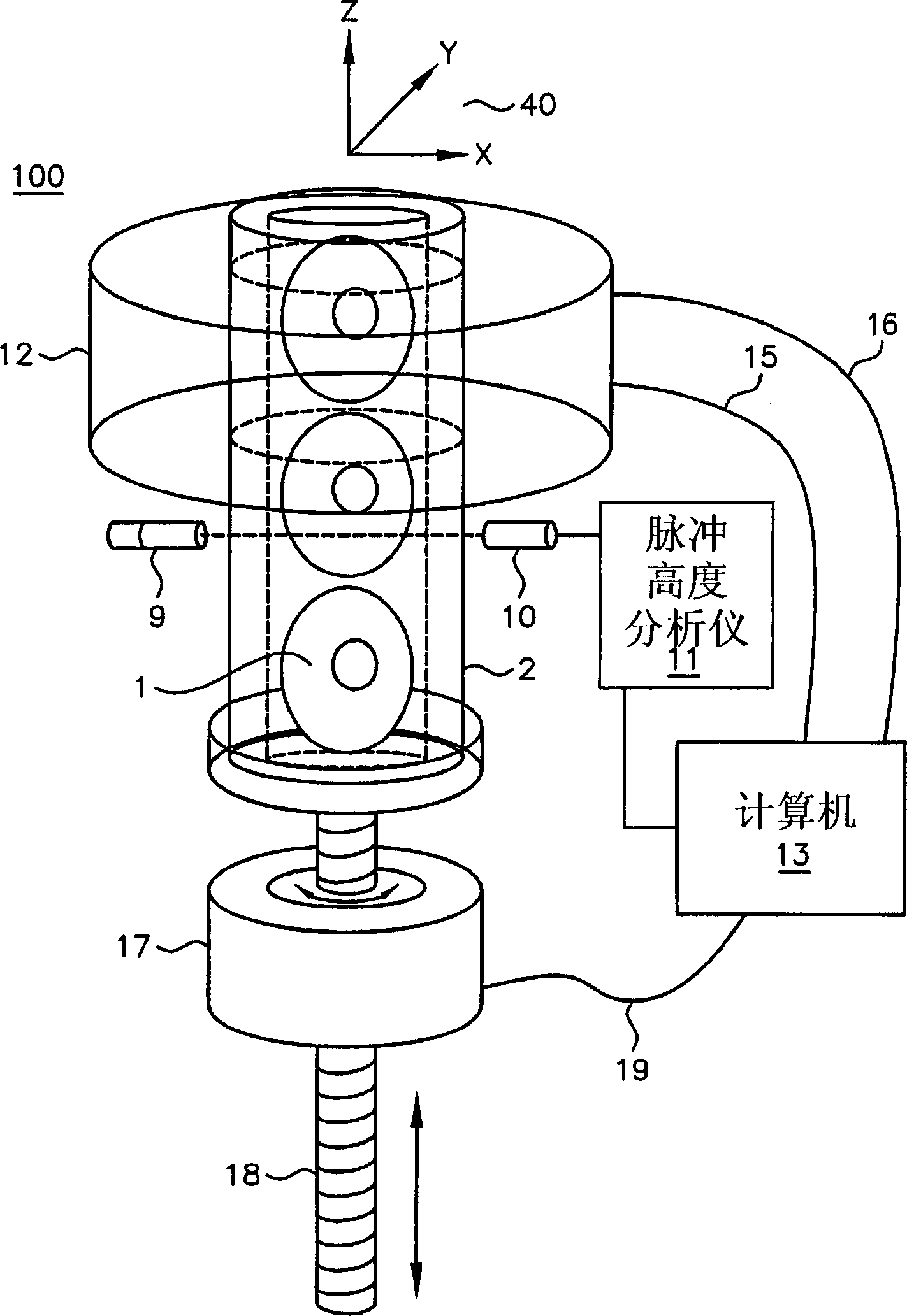
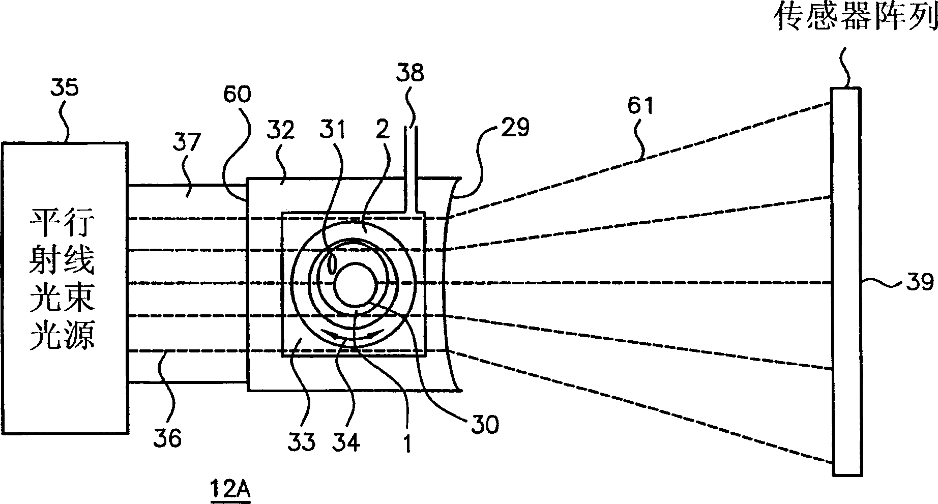
Optical tomography of small objects using parallel ray illumination and post-specimen optical magnification

An optical tomography, parallel beam technology, applied in material analysis using radiation, material analysis using wave/particle radiation, and material analysis by optical means, can solve the deterioration of reconstructed image quality and the difficulty of two-dimensional projection images. Reflection and other problems, to achieve the effect of easy control, high signal-to-noise ratio, and lightening of imaging samples

Inactive Publication Date: 2006-01-11
VISIONGATE
View PDF3 Cites 15 Cited by
  • Summary
  • Abstract
  • Description
  • Claims
  • Application Information

AI Technical Summary

Problems solved by technology

Different source-specimen distances between source-detector pairs lead to worsened reconstructed image quality
Difficult to visualize in 2D projection images or radiography because projection magnification varies through object space in cone beam imaging
For example, it is difficult to directly extract diagnostic-relevant features from projected images

Method used


Image

  • Optical tomography of small objects using parallel ray illumination and post-specimen optical magnification
  • Optical tomography of small objects using parallel ray illumination and post-specimen optical magnification
  • Optical tomography of small objects using parallel ray illumination and post-specimen optical magnification

Examples


Embodiment Construction

[0040] The invention is described herein with reference to specific examples relating to biological cells. However, it will be understood that these examples are for illustrating the principles of the invention and the invention is not limited thereto. In one example, constructing a three-dimensional distribution of optical density within a microscopic volume allows the quantification and location of structures, molecules or molecular probes of interest. By using labeled molecular probes, the number of probes attached to specific structures in microscopic objects can be measured. For purposes of illustration, an object, such as a biological cell, can be labeled with at least one colored or labeled molecular probe, and the measurement and location of the probe yields important information about the disease state of the cell, including ( But not limited to) various cancers such as lung, breast, prostate, neck and ovarian cancers.

[0041] A feature of the invention is that the...


PUM


Abstract

A parallel-beam optical tomography system (4) for imaging an object of interest (1) includes a parallel ray beam radiation source (35) that illuminates the object of interest (1) with a plurality of parallel radiation beams (36). After passing through the object of interest (1) the pattern of transmitted or emitted radiation intensities is magnified by a post specimen optical element or elements. An object containing tube (2) is located within an outer tube (32), wherein the object of interest (1) is held within or flows through the object containing tube (2). A motor (34) may be coupled to rotate and / or translate the object containing tube (2) to present differing views of the object of interest (1). One or more detector arrays are located to receive the emerging radiation (68) from the post specimen magnifying optic. Two- or three-dimensional images may be reconstructed from the magnified parallel projection data.

Description

[0001] related application [0002] This application is a continuation-in-part of Alan C. Nelson's US Patent No. 6,522,775, entitled "APPARATUS AND METHOD FOR IMAGING SMALLOBJECTS IN A FLOW STREAM USING OPTICAL TOMOGRAPHY," published February 18, 2003. [0003] This application is also related to US Patent Application 6,591,003, published July 8, 2003, to Chu, entitled "OPTICALTOMOGRAPHY OF SMALL MOVING OBJECTS USING TIMEDELAY AND INTEGRATION IMAGING." technical field [0004] The present invention relates generally to optical tomography (OT) imaging systems, and more particularly to parallel beam optical tomography (PBOT), in which small objects are illuminated, for example, with an intense parallel beam of light in the visible or ultraviolet portion of the electromagnetic spectrum (such as biological cells), and through post-specimen magnification optics to produce a magnified transmitted or emitted projected image. Background technique [0005] US Application 10 / 126,026,...

Claims


Application Information

Patent Timeline
Patent Type & Authority Applications(China)
IPC IPC(8): G06K9/00G01N15/14G01N21/03G01N21/05G01N21/17G01N21/59G01N21/64G01N21/78G01N23/04G01N33/543G01N33/554G01N33/60G06T1/00G06T3/00G06T11/00
CPCG01N21/0303G01N2021/5919G01N21/6428G01N15/147G01N21/6456G01N21/4795G06T11/006G01N2021/5923G01N21/05G01N2021/0307G01N15/14G01N2021/052G01N2021/5957G01N2021/1787G01N23/046G01N2021/1772G01N2201/0696G01N2021/0392G01N2223/419
Inventor R·H·约翰逊A·C·尼尔森
Owner VISIONGATE
Why Eureka
Try Eureka