Injection circuit with external predistortion

A predistortion signal, injection circuit technology, applied in the field of linearization, can solve the problems of high cost of broadband signal combiner, can not effectively prevent attenuation, weaken the compensation effect, etc., to achieve low distortion injection, eliminate distortion and memory effects , the effect of reducing complexity

Active Publication Date: 2006-02-01
SANECHIPS TECH CO LTD
View PDF0 Cites 1 Cited by
  • Summary
  • Abstract
  • Description
  • Claims
  • Application Information

AI Technical Summary

Problems solved by technology

However, the frequency range that the usual envelope injection method can be limited to compensation has a great limitation: at the low end of the frequency, since the influence of the DC bias signal of the amplifier tube on the envelope injection circuit must be isolated by a DC blocking capacitor, so Very low envelope injected signals will be blocked by this DC blocking capacitor; at the high end of frequency, a large capacitor (usually nF level) at the input of the amplifier tube to filter DC ripple will severely attenuate high frequencies (up to Several megahertz) envelope injection signal, weakening its compensation effect
but figure 2 The problem with the injection circuit shown is that the high-frequency choke coil 206 between the envelope signal and the DC signal cannot effectively prevent the attenuation of the high-frequency components of the envelope signal by the decoupling capacitor 208, and the broadband signal combiner Expensive and inconvenient to use

Method used


Image

  • Injection circuit with external predistortion
  • Injection circuit with external predistortion
  • Injection circuit with external predistortion

Examples


Embodiment Construction

[0013] The present invention will be further described in detail below in conjunction with the accompanying drawings.

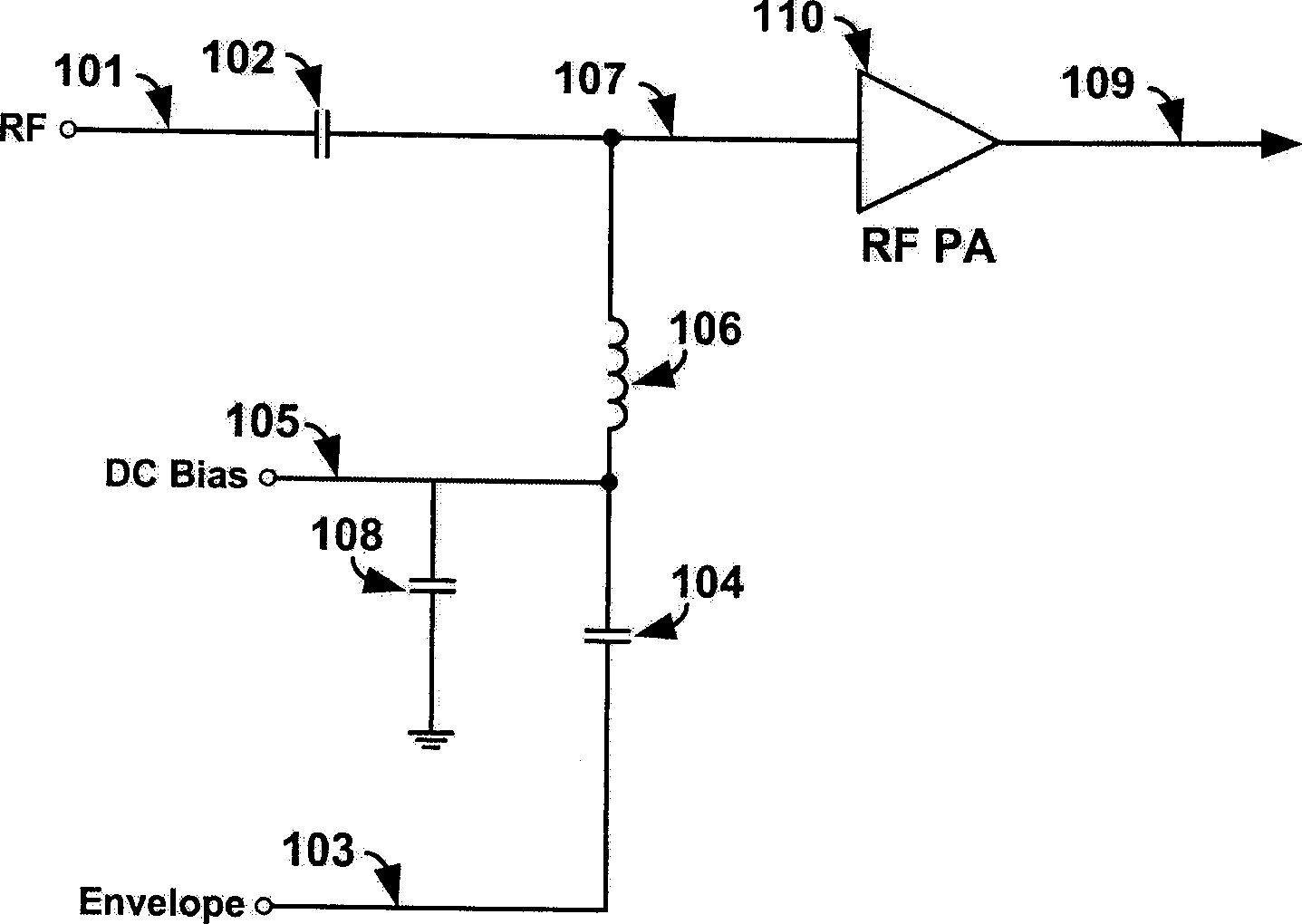
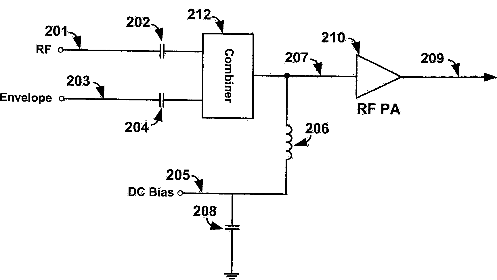
[0014] figure 1 and figure 2 It has already been explained in the background art.

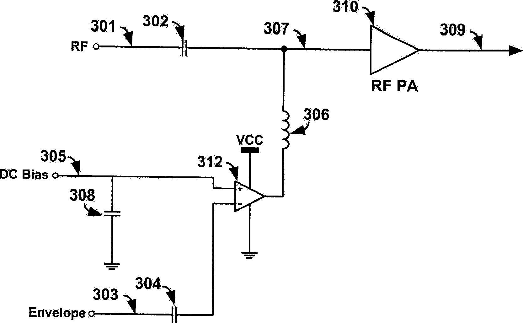
[0015] image 3 It is a circuit diagram of the out-of-band predistortion signal injection circuit proposed by the present invention. Such as image 3 Shown: the out-of-band predistortion signal injection circuit proposed by the present invention includes DC blocking capacitor 302, DC blocking capacitor 304, high frequency choke coil 306, decoupling capacitor 308 and RF power amplifier 310; RF input signal 301 is passed through DC blocking After the capacitor 302 is output to the input end of the radio frequency power amplifier 310;

[0016] The circuit also includes an operational amplifier 312 with high input impedance; a DC bias signal 305 is input to the non-inverting input terminal of the operational amplifier 312; one end of the decoupling capacitor 308 is connected...


PUM


Abstract

The disclosed circuit includes DC isolated capacitor, high frequency choking winding, decoupling capacitor and radio frequency power amplifier. Being passed through DC isolated capacitor, the input signal in radio frequency is output to the input end of the radio frequency power amplifier. The circuit also includes an operational amplifier with high input impedance. A DC bias signal is input to the positive input end of the operational amplifier. Being cascaded to the DC isolated capacitor, envelope signal is connected to negative input end of the operational amplifier. Being cascaded to high frequency choking winding, output end of the operational amplifier is connected to input end of the radio frequency power amplifier, output signal of which is the output of the disclosed circuit. The invention isolates envelope signal in low frequency from DC signal, expands applicable area of frequency suitable to linearization method of envelope injection, and lowers cost of system greatly.

Description

technical field [0001] The invention relates to the linearization technology of the high-frequency amplifier in the communication system, in particular to the injection technology of the out-of-band predistortion signal. Background technique [0002] In recent years, with the rapid development of wireless communication around the world, wireless spectrum resources are becoming increasingly scarce. In order to utilize limited spectrum resources more effectively, many wireless communication systems adopt linear modulation with higher spectrum utilization efficiency. Since both phase and amplitude of a linearly modulated signal carry useful information, any nonlinear amplification of such a signal will result in an increase in the bit error rate and interference to adjacent wireless channels. Both of these adverse effects should be avoided when designing a wireless communication system, so linear modulation signals must require high linearity amplification. [0003] The nonli...

Claims


Application Information

Patent Timeline
Patent Type & Authority Applications(China)
IPC IPC(8): H03F1/32H03F3/189
Inventor 刘晓伟茹洪涛
Owner SANECHIPS TECH CO LTD
Why Eureka
Try Eureka