Mold type coater coating method and photolithagraphic protector adhesive film assembly made therefrom

A coating method and technology of the coater, which are applied to the device for coating liquid on the surface, the original for photomechanical treatment, optics, etc., can solve the problems of becoming foreign matter, difficult to remove, and difficult to ensure the obtaining of coating film, etc.

Active Publication Date: 2006-02-22
SHIN ETSU CHEM IND CO LTD
View PDF2 Cites 2 Cited by
  • Summary
  • Abstract
  • Description
  • Claims
  • Application Information

AI Technical Summary

Problems solved by technology

[0020] In addition, regarding the foreign matter or coating material remaining on the surface of the roller, the roller that discharges the coating liquid from the front end of the mold for the preliminary operation is roughly cleaned and regenerated each time, but the cleaning and regeneration process cannot completely remove the foreign matter or coating material. There are also many cases of dry or solid objects reattaching from the rollers.
[0021] In addition, during long-term use, dry or solid matter of the coating material may adhere to the periphery of the discharge slit, and it is difficult to remove it by preliminary operations, and these may occasionally peel off and become foreign matter
[0022] Due to the above-mentioned circumstances, the current situation of the coating method using a die-type applicator is that a sufficiently satisfactory technique has not been found that can apply a preliminary work to the front end of the die without foreign matter adhering, and as a result, it is difficult to guarantee the obtained Coating film with very little foreign matter
[0023] Moreover, based on the above reasons, when manufacturing a pellicle film that requires less foreign matter in particular, the spin coating method is necessary, and it is difficult to use a die coater.
In addition, it is difficult to obtain large-scale protective film and protective film components with less foreign matter at low cost

Method used


Image

  • Mold type coater coating method and photolithagraphic protector adhesive film assembly made therefrom
  • Mold type coater coating method and photolithagraphic protector adhesive film assembly made therefrom
  • Mold type coater coating method and photolithagraphic protector adhesive film assembly made therefrom

Examples


Embodiment 1

[0118] Examples of the present invention will be described below, but the present invention is not limited to the examples.

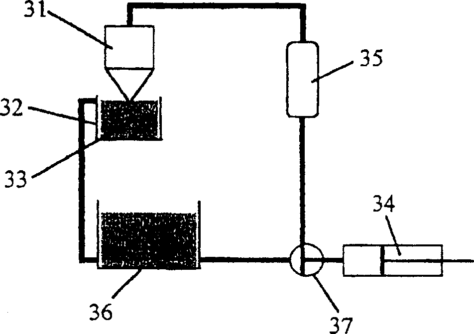
[0119] The die coater used in this example was used in Figure 6 The juxtaposition shown image 3 Applicator piping shown, also configure Figure 4 (a) Ultrasonic vibrating plate shown. The mold 61 is made of SUS304, the coating width is 796 mm, and the slit gap is 0.3 mm. The fluorine-based solvent used for the coating liquid: CT-Solv (manufactured by Asahi Glass Co., Ltd., product name) and the fluorine-based polymer: SAITOP (manufactured by Asahi Glass Co., Ltd. Product name) was diluted to 9%, and the film-forming substrate was smooth and ground double-sided 800×920×8(t)mm synthetic quartz. In addition, all the devices were installed in a class 10 clean room.

[0120] In the structure shown above, the mold 61 immersed in the mold drying prevention plate 65 was irradiated with ultrasonic waves of 40 kHz for 5 minutes before starting the coating, ...


PUM


Abstract

The invention aims to establish a maintenance management method of the die in a die coater and produce a large-size protection glue film subassembly with an extremely-low content of foreign matters with low costs. In order to achieve the purpose, the invention provides a coating method for die coaters, which comprises allowing the front end of the die to be immersed and contacted with a coating solution stored in a container; holding the die as lifted above the coating solution until the drops of the coating solution slowly hanging from the front end of the die disappear by dint of the surface tension of the coating solution; and ejecting the coating solution onto a substrate for coating. When the coating operation is not performed, it is preferable that the die is usually immersed or contacted with the coating solution, the coating solution is ejected continuously or intermittently from the front end of the die after passing a filter, and the die immersed in the coating solution is subjected to ultrasonic cleaning.

Description

technical field [0001] The invention relates to a coating method of a mold type coater and a photolithographic protective film assembly manufactured by the method. Background technique [0002] In the manufacture of LSI or liquid crystal panels, etc., there is a process of making patterns on semiconductor wafers or original plates for liquid crystals by photolithography. At this time, protective film components are used as dust protection devices for photomasks or shrink shields (reticle). . [0003] In the case of using the pellicle film assembly, because the foreign matter does not directly adhere to the surface of the photomask but adheres to the pellicle film assembly, as long as the focus is on the pattern of the photomask during photolithography, the particles on the pellicle film assembly The foreign matter becomes irrelevant to the transfer of the pattern. [0004] In terms of the structure of this protective film assembly, a transparent protective film made of cel...

Claims


Application Information

Patent Timeline
Patent Type & Authority Applications(China)
IPC IPC(8): B05C5/00
CPCB05C5/0254B05D1/265Y10T428/3154Y10T428/31971G03F1/62B05B1/005
Inventor 关原一敏
Owner SHIN ETSU CHEM IND CO LTD
Why Eureka
Try Eureka