Superconductive magnet system for intercurrent treatment three-dimensional position

A technology of stereotaxic positioning and superconducting magnets, applied in superconducting magnets/coils, treatment, catheters, etc., can solve problems such as high operating costs, complex structures, and inconvenient system operations, and achieve reduced system operating costs and convenient and reliable installation Effect

Active Publication Date: 2006-03-15
INST OF ELECTRICAL ENG CHINESE ACAD OF SCI
View PDF0 Cites 7 Cited by
  • Summary
  • Abstract
  • Description
  • Claims
  • Application Information

AI Technical Summary

Problems solved by technology

[0005] In order to overcome the shortcomings of the existing superconducting magnet system for surgery, such as complex structure, high operating cost, and inconvenient system operation, the present invention proposes a new superconducting magnet system for surgery, which uses a high-temperature superconducting magnet, and the magnet system operates In a cryogenic system protected by solid nitrogen

Method used


Image

  • Superconductive magnet system for intercurrent treatment three-dimensional position
  • Superconductive magnet system for intercurrent treatment three-dimensional position
  • Superconductive magnet system for intercurrent treatment three-dimensional position

Examples


Embodiment Construction

[0016] The present invention will be further described below in conjunction with the accompanying drawings and embodiments.

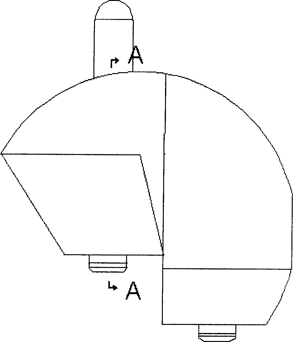
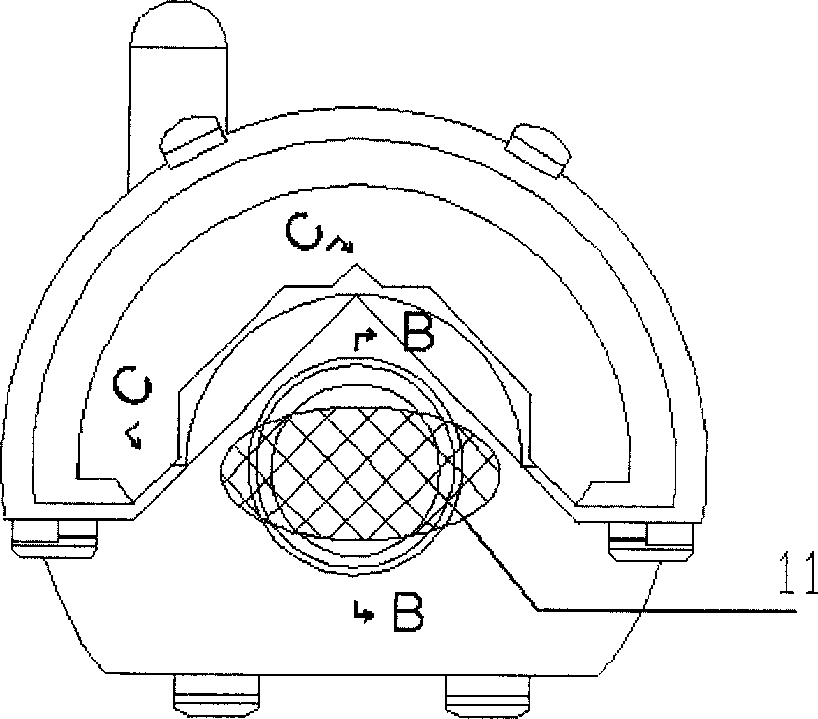
[0017] Figure 1a , 1b are the left view and the front view of the appearance of the superconducting magnet system of the present invention, respectively, and 11 in Figure b is a schematic diagram of the open area surrounded by the magnet system, that is, the area where brain surgery is performed.

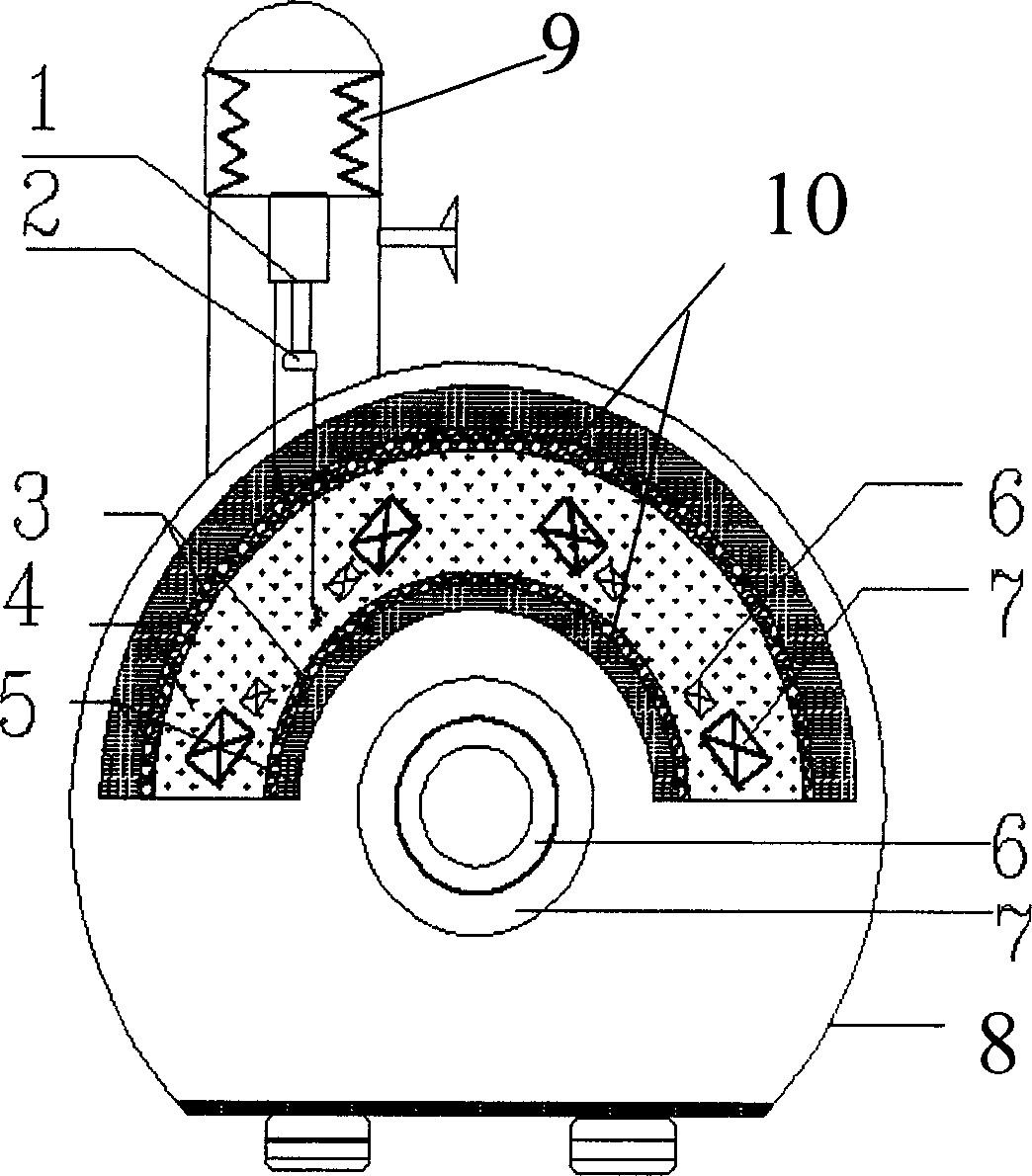
[0018]Figures 2a, 2b, and 2c are cross-sectional views of specific embodiments of the present invention along section lines A-A, B-B, and C-C, respectively. As shown in the figure, the structure of the superconducting magnet system of the present invention includes superconducting coils 6 and 7, solid nitrogen 4, multi-layer heat insulating material 3, multi-layer radiation shield 10, liquid nitrogen 5, and cryogenic Dewar from inside to outside. 8. G-M refrigerator9. The solid nitrogen 4 that fills the space of the superconducting coils 6 and 7 wraps the ...


PUM

PropertyMeasurementUnit
current densityaaaaaaaaaa

Abstract

A super-conducting magnetic system for the 3D location in insert therapy is composed of a high-temp super-conducting magnet unit consisting of three pairs of superconducting solenoid coils divided into internal and external layers, a G-M refrigerating unit, a low-temp cylinder, a superconductor-loss protector and a program controlled power supply. The whole magnet unit forms a symmetrical open space. The magnetic system is running in a low-temp system protected by solidified nitrogen.

Description

Technical field [0001] The invention relates to a superconducting magnet, in particular to a superconducting magnet system used for stereotaxic positioning of neurosurgical interventional treatment. Background technique [0002] In conventional interventional therapy, catheters are inserted into arteries or veins through the skin of the human body, and the movement of the catheter is achieved by applying force to the rear end of the catheter. Therefore, the catheter must be made of very hard materials to ensure The catheter will not be bent during the advancement process, but because the catheter is relatively hard, if the path is complicated, the catheter often cannot reach the destination. Therefore, in some important parts of the human body (such as the heart, brain), conventional interventional therapy is full of challenges and complexity, because its operation is difficult to control, and often requires skilled experts to spend several hours. Therefore, improving the o...

Claims


Application Information

Patent Timeline
Patent Type & Authority Applications(China)
IPC IPC(8): A61M25/01A61M25/08A61M31/00A61M36/00H01F6/00
Inventor 王秋良白烨
Owner INST OF ELECTRICAL ENG CHINESE ACAD OF SCI
Why Eureka
Try Eureka