Unstable laser cavity tunned by grating

A laser resonator, unstable technology, applied in the field of lasers, can solve the problems of large resonator loss, difficult to manufacture, easy to damage, etc., and achieve the effect of low cavity loss

Inactive Publication Date: 2006-04-19
INST OF ELECTRONICS CHINESE ACAD OF SCI
View PDF0 Cites 9 Cited by
  • Summary
  • Abstract
  • Description
  • Claims
  • Application Information

AI Technical Summary

Problems solved by technology

This system has the following disadvantages: 1. The loss of the resonant cavity adopting this composite optical system is relatively large
2. The grating is

Method used


Image

  • Unstable laser cavity tunned by grating
  • Unstable laser cavity tunned by grating
  • Unstable laser cavity tunned by grating

Examples


Embodiment Construction

[0027] In order to further illustrate the features and structures of the present invention, the present invention will be described in detail below in conjunction with the accompanying drawings.

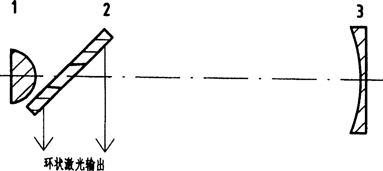
[0028] refer to figure 1 Schematic diagram of a confocal positive branch unstable cavity usually without tuning. The resonant cavity consists of a convex spherical reflector 1, a 45° planar out-coupling reflector 2 with a central hole and a concave spherical reflector 3. The radius of curvature of the convex spherical mirror is R 1 , is a diverging mirror with focal length f 1 =R 1 / 2; the radius of curvature of the concave spherical mirror 3 is R 2 , which is a converging mirror with focal length f 2 =R 2 / 2. The distance between the convex spherical reflector 1 and the concave spherical reflector 3 is L. The 45° planar out-coupling mirror 2 with a central hole is located near the convex spherical mirror 1, and the central part has a hole with a diameter a, and the axis of t...


PUM


Abstract

The invention is suitable to tuning unstable laser cavity in high power through grating. The laser cavity is composed of convex spherical reflector, concave spherical reflector with center hole and composite converging optical system of grating behind the concave spherical reflector. The convex spherical reflector, the concave spherical reflector and the composite converging optical system of grating are aligned along a common optical axis. There is a Littrow angle between normal of grating and optical axis. The grating is a reflecting concave spherical diffraction grating or reflecting plane diffraction grating. Advantages are: low dissipation of laser cavity, high output laser energy and laser power. The invention is applicable to multiple turnable lasers including carbon dioxide laser, carbon monoxide laser, hydrogen fluoride / deuterium fluoride laser etc. There is wide applied foreground in areas of laser chemistry, processing and radar, and atmospheric propagation etc.

Description

technical field [0001] The invention relates to the technical field of lasers, in particular to an unstable laser cavity suitable for high-power grating tuning. Background technique [0002] High power lasers such as CO 2 Lasers often use unstable laser resonators. In some important applications, the wavelength of the laser output needs to be tunable. The existing tunable technology is to replace the concave spherical mirror with a convex lens-reflective plane diffraction grating compound optical system (references: R.Barbini, A.Ghigo, A.Palucci, S.Ribezzo.Line tunable TEA CO 2 laser using SFUR configuration. Optics Communications, 1988, 68(1): 41-44). This system has the following disadvantages: 1. The resonant cavity using this composite optical system has a relatively large loss. This is because both surfaces of the convex lens need to be coated with an anti-reflection film, and the reflectivity of the grating, that is, the efficiency of the grating, cannot be very hi...

Claims


Application Information

Patent Timeline
IPC IPC(8): H01S3/08
Inventor 于延宁万重怡
Owner INST OF ELECTRONICS CHINESE ACAD OF SCI
Why Eureka
Try Eureka