Real-time detector for laser beam quality factor M2

A laser beam quality and real-time detection technology, applied in the field of detectors, can solve the problems of difficult phase distribution measurement, inability to realize real-time detection, cumbersome operation, etc., and achieve the effect of convenient manufacture, compact structure and small volume

Inactive Publication Date: 2006-05-03
SHANGHAI INST OF OPTICS & FINE MECHANICS CHINESE ACAD OF SCI
View PDF0 Cites 15 Cited by
  • Summary
  • Abstract
  • Description
  • Claims
  • Application Information

AI Technical Summary

Problems solved by technology

Beam quality M 2 The measurement methods of factors can be divided into two categories according to the principle: one is the Fourier transform method, which simultaneously measures the light field intensity distribution and phase distribution on the beam waist section, and then obtains the spatial spectrum by Fourier transform. Difficult, this method is seldom used; the other is more commonly used, which is the beam width measurement method based on the beam propagation equation, which is also the recommended method of the current ISO standard. There are many ways to use this method to measure the beam quality of the laser beam. However, most methods need to accurately find the beam waist position, and must perform multi-point measurement, so real-time detection cannot be realized
The beam quality M can be measured in real time by using the method of eccentric Fresnel lens group 2 factor, but its design is complicated and the operation is cumbersome. At the same time, different lenses need to be designed for laser beams with different beam qualities, and all measurements cannot be completed by a single lens group.

Method used


Image

  • Real-time detector for laser beam quality factor M2
  • Real-time detector for laser beam quality factor M2
  • Real-time detector for laser beam quality factor M2

Examples


Embodiment Construction

[0019] The present invention will be further described below in conjunction with the accompanying drawings and embodiments, but the protection scope of the present invention should not be limited thereby.

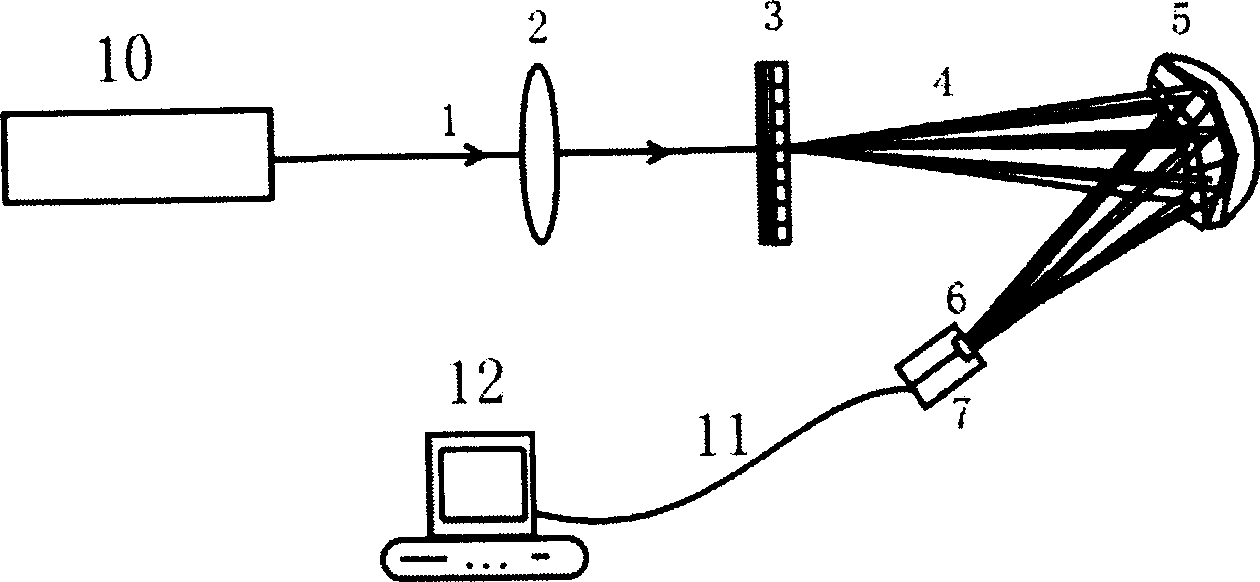
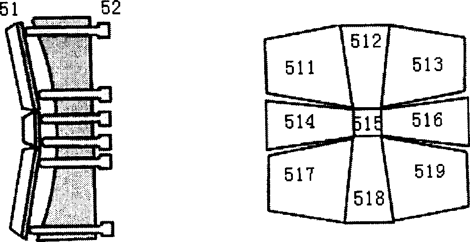
[0020] see first figure 1 , figure 1 It is a structural schematic diagram of the laser beam quality factor real-time detector of the present invention. As can be seen from the figure, the composition of the laser beam quality factor real-time detector of the present invention is: a focusing lens 2, a grating group 3, an optical path adjuster 5, and a CCD 7 that are sequentially arranged on the same optical path in the advancing direction of the laser beam 1 to be measured that the laser 10 emits , the output end of the CCD7 is connected to the computer 12 through the signal line 11, the focal length of the focusing lens 2 is f, and the diameter is D, and the grating group 3 is composed of two gratings placed close to each other in an orthogonal manner The compact grating ...


PUM


Abstract

The invention relates to a laser beam quality M2 factor real time tester, which is formed by a focusing lens, a grid group, a light path adjuster and a CCD, wherein the output end of the CCD is connected with the computer by signal wire; the focus of the focusing lens is f; the dilemma is D; the grid group is a grid light-dividing system which is formed by two oppressed blocks of grid; the grid light-dividing system can divide a beam laser into 3í‡3 strips light beam groups with isocandela; the light path adjuster includes a lens array which is formed by nine reflecting lenses with the corresponding micro-adjusting screw; the distance from the grid group, the light path adjuster to the receiving side of the CCD of the zero-grade diffracted beam of the focusing lens equals to the focus of the focusing lens.

Description

technical field [0001] The invention relates to a detector, in particular to a laser beam quality M 2 Factor real-time detector. Background technique [0002] Laser beam quality M 2 The factor is an important technical index describing the characteristics of the laser, which is directly related to the application efficiency of the laser. m 2 The factor describes the difference between the actual beam and the ideal fundamental mode Gaussian beam, which is defined as [0003] M 2 = π 4 λ d w θ f [0004] Among them, d w and θ f represent the beam waist width and far-field divergence angle of the actual beam, respectively, and 4λ / π is the product of the beam waist width and the far-field divergence angle of the ideal Gaussian beam. Beam quality M 2 The measurement methods of factors ca...

Claims


Application Information

Patent Timeline
Patent Type & Authority Applications(China)
IPC IPC(8): G01J1/00
Inventor 房滔叶訢徐剑秋
Owner SHANGHAI INST OF OPTICS & FINE MECHANICS CHINESE ACAD OF SCI
Why Eureka
Try Eureka