Distributed optical fiber mode coupling biochemical sensor, optical fiber link, and sensing system

A distributed optical fiber, biochemical sensor technology, applied in the fields of biology, chemistry, and optical fiber sensing, can solve the problem that the long-period fiber grating resonant center wavelength has a great influence of environmental temperature changes, the precise determination of the resonant center wavelength is difficult, and it is difficult to distribute chemical and chemical sensors. Bio-sensing and other issues, to achieve the effect of compact structure, simple debugging and simple structure

Inactive Publication Date: 2006-05-10
重庆工学院
View PDF0 Cites 11 Cited by
  • Summary
  • Abstract
  • Description
  • Claims
  • Application Information

AI Technical Summary

Problems solved by technology

However, the optical fiber biosensor also has the following disadvantages: (1) the sensor and its sensing system adopt a single optical path intensity measurement method, and the fluctuation and interference of the light source, optical path and circuit system will affect the accuracy of the sensing results; (2) the long-term The resonant wavelength band of periodic fiber gratings is wide and flat, and it is very difficult to accurately determine the resonant center wavelength; (3) the drift of the resonant center wavelength of long-period fiber gratings is greatly affected by the change of ambient temperature, and it is necessary to carry out the measurement of the sensor and the measured object. Constant temperature control; (4) It is difficult to use (dense) wavelength division multiplexing and space division multiplexing technology to realize large-scale distributed chemical and biological sensing

Method used


Image

  • Distributed optical fiber mode coupling biochemical sensor, optical fiber link, and sensing system
  • Distributed optical fiber mode coupling biochemical sensor, optical fiber link, and sensing system
  • Distributed optical fiber mode coupling biochemical sensor, optical fiber link, and sensing system

Examples


Embodiment Construction

[0017] Taking the measurement of the protein concentration of human immunoglobulin G (IgG) as an example, the implementation of the above-mentioned sensor, optical fiber link and sensing system thereof is further described in conjunction with the accompanying drawings, and the measurement of chemical components or biomolecules in the form of other gases or solutions The implementation is similar, except that a different biomolecular or chemical composition-sensitive film is cured on the cladding of each section of optical fiber.

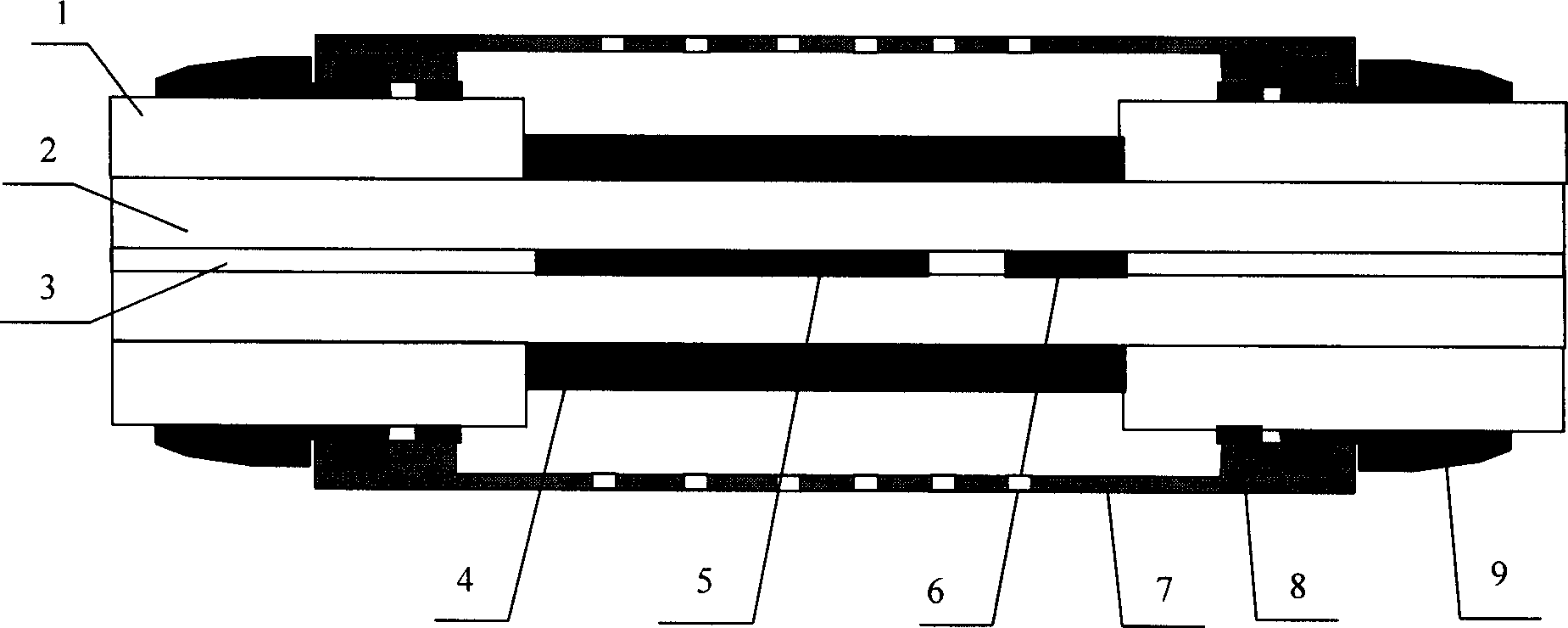
[0018] see figure 1 , the structure of the distributed optical fiber mode-coupled biochemical sensor includes: optical fiber coating layer 1, optical fiber cladding layer 2, optical fiber core 3, biomolecular sensitive film layer 4, long-period fiber Bragg grating LPFG 5, fiber Bragg grating FBG 6, protection Set 7, curing glue 8, transition buffer set 9. The manufacturing method is: (1) removing a section of plastic protective coating of an optical...


PUM

PropertyMeasurementUnit
couplingaaaaaaaaaa
thicknessaaaaaaaaaa
thicknessaaaaaaaaaa

Abstract

The invention discloses a distributed fiber coupling biochemistry sensor and corresponding fiber link circuit and sensing system. The inventive sensor as basic sensing unit of sensing system comprises a long period fiber grating, Bragg fiber grating and absorbing or sensing film for chemical or biochemical molecule; a plurality of such basic sensing unit connected serially with sequence and direction forming the fiber link circuit. Sensing system comprises the fiber link circuit and broad band light source, broad band coupler, initial Bragg fiber grating, fiber light spectrum demodulator and computer. The invention is characterized in that it takes wavelength-division multiplex to realize distributed sensing and has the advantages of simple and reliable.

Description

technical field [0001] The invention belongs to the technical fields of optical fiber sensing, biology and chemistry, and in particular relates to a distributed optical fiber mode coupling biochemical sensor, an optical fiber link and a sensing system. Background technique [0002] Optical fiber chemical and biological sensor is a new type of sensing technology born in the mid-1970s. It solidifies substances that can identify and transduce chemical or biomolecules on optical fibers, and performs selective chemical or biomolecular recognition of the measured substances. , and then converted into various optical information to obtain chemical and biological information. In most sensors, the optical fiber only plays the role of light transmission, and some sensors are based on the change of the measured substance directly affecting the properties of the optical fiber waveguide for sensing. Optical fiber chemical and biological sensors have many advantages, such as high informa...

Claims


Application Information

Patent Timeline
Patent Type & Authority Applications(China)
IPC IPC(8): G01N21/41G01N33/48
Inventor 曾祥楷
Owner 重庆工学院
Why Eureka
Try Eureka