
Conductive composition exhibiting PTC behavior and over-current protection device using the same

A conductive composite material and positive temperature coefficient technology, which is applied in the direction of resistors with positive temperature coefficient, conductive materials dispersed in non-conductive inorganic materials, electrical components, etc., can solve the problem that resistance reproducibility is difficult to control and cannot be effectively reduced Resistance value, poor adhesion, etc.

Inactive Publication Date: 2006-05-24
POLYTRONICS TECH
View PDF0 Cites 4 Cited by
  • Summary
  • Abstract
  • Description
  • Claims
  • Application Information

AI Technical Summary

Problems solved by technology

However, since ceramic powder does not have a concave-convex surface unlike carbon black, and its adhesion to polymers such as polyolefins is worse than that of carbon black, its resistance reproducibility is also difficult to control
In order to increase the adhesion between polyolefin polymers and metal particles, conventional conductive composite materials that use ceramic powder as conductive filler will add a coupling agent, such as: anhydride compounds or silane compounds, to strengthen polyolefin polymerization. Adhesion between objects and metal particles, but the addition of coupling agent can not effectively reduce the overall resistance value

Method used

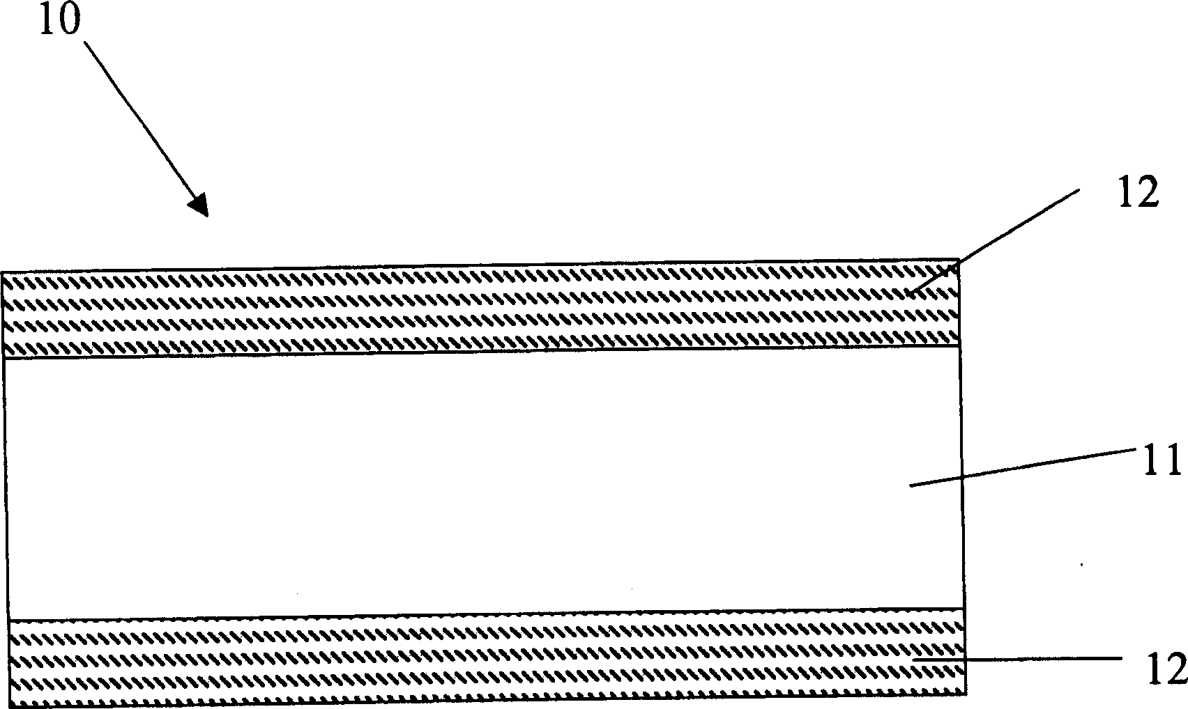

Image

  • Conductive composition exhibiting PTC behavior and over-current protection device using the same

Examples


Embodiment 1

[0017] The formulation ingredients used in Example 1 are shown in Table 2. The feed temperature of the batch mixer (Hakke-600) is set at 160°C, and the feed time is 2 minutes. The feed program is to add a certain amount of high-density polyethylene first, stir for a few seconds, and then add conductive filler (nickel powder and conductive carbon black). The rotational speed of the mixer rotation was 40 rpm. After 3 minutes, the rotating speed was increased to 70 rpm, and the kneading was continued for 7 minutes before feeding to form a conductive composite material with positive temperature coefficient characteristics.

[0018] Put the above-mentioned conductive composite material into a mold with a steel plate as the outer layer and a middle thickness of 0.25mm in a symmetrical manner up and down. Put a layer of Teflon release cloth on the top and bottom of the mold, pre-press for 3 minutes, and the pre-press operating pressure is 50kg / cm 2 , the temperature is 180°C. Pr...

Embodiment 2

[0020] The steps for preparing the PTC element are the same as in Example 1, but the volume percentage of high-density polyethylene is reduced from 57 to 54. In addition, a coupling agent (Capow-12) is added between the step of adding high-density polyethylene and the step of adding conductive filler. Stir for several seconds before and after adding the coupling agent. The volume percentage of the coupling agent is 3. The formulation of the conductive composite material of this embodiment and the electrical characteristics of the PTC element are shown in Table 2.

Embodiment 3

[0022] The steps for preparing the PTC element are the same as in Example 1, but the volume percentage of high-density polyethylene is reduced from 57 to 47. In addition, while adding high-density polyethylene, add carboxyl resin (MB-100D), the volume percentage of the carboxyl resin is 10. The formulation of the conductive composite material of this embodiment and the electrical characteristics of the PTC element are shown in Table 2.


PUM

PropertyMeasurementUnit
melting pointaaaaaaaaaa
percent by volumeaaaaaaaaaa

Abstract

The invention discloses a conductive composite material, which includes a plurality of polymers and at least one conductive filler. The plurality of polymers are compatible with each other on a molecular scale, and the shape of the conductive filler is sheet instead of filament. The conductive composite material of the present invention has better electrical properties than conventional conductive composite materials having only a single polymer component. The invention also discloses an overcurrent protection element, which comprises two metal foils and a positive temperature coefficient PTC material layer, and the PTC material layer comprises the conductive composite material.

Description

technical field [0001] The present invention relates to a conductive composite material with a positive temperature coefficient, more particularly, relates to a conductive composite material with a positive temperature coefficient applied to an overcurrent protection element. The invention also relates to an overcurrent protection element comprising the conductive composite material with a positive temperature coefficient. Background technique [0002] Since the resistance of conductive composite materials with positive temperature coefficient (Positive Temperature Coefficient: PTC) has the characteristics of sensitive response to temperature changes, it can be used as a current sensing element, and has been widely used in overcurrent protection elements or circuit elements. . Because the resistance of the PTC conductive composite material can maintain an extremely low value at normal temperature, the circuit or battery can operate normally. However, when an over-current o...

Claims


Application Information

Patent Timeline
Patent Type & Authority Applications(China)
IPC IPC(8): H01B1/20H01C7/02H01C7/13
CPCH01B1/24H01C7/027
Inventor 马云晋蔡东成陈国勲
Owner POLYTRONICS TECH
Learn More