

Gradient pushing and enlarging device
A squeeze-expanding device, gradient technology, applied in drilling equipment, drilling equipment and methods, sheet pile walls, etc., to achieve the effects of light weight, improved work efficiency, and high speed
- Summary
- Abstract
- Description
- Claims
- Application Information
AI Technical Summary
Problems solved by technology
Method used
Image

Examples
Embodiment Construction
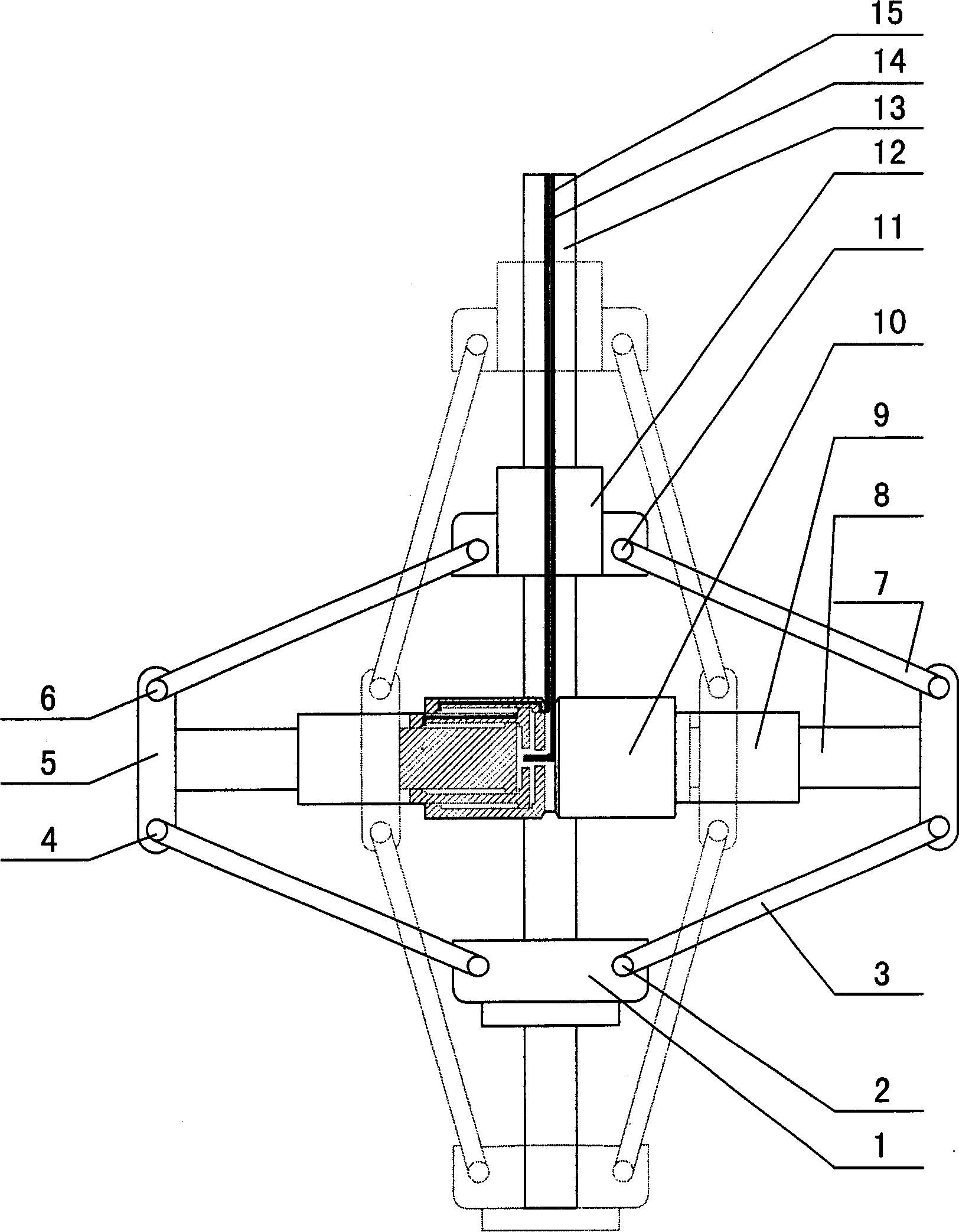
[0009] Such as figure 1 As shown: the connecting rod 13 has two built-in high-pressure oil inlet pipes 14 and two oil outlet pipes 15, which are connected with the large gradient oil cylinder 10; The arm 5 is connected, the middle extrusion arm 5 is connected with the upper extrusion arm 7 through the pivot pin 6, the upper extrusion arm 7 is connected with the upper connecting plate 12 through the pivot pin 11, and the upper connecting plate 12 is socketed with the connecting rod 13, The middle extruding and expanding arm 5 is connected with the lower extruding and expanding arm 3 through the pivot pin 4, and the lower extruding and expanding arm 3 is connected with the lower connecting disc 1 through the pivot pin 2, and the lower connecting disc 1 is socketed with the connecting rod 13.
[0010] This device works like this: when the oil is being squeezed and expanded, the oil inlet pipe 14 enters the oil, pushes the middle oil cylinder 9 and the piston rod 8 to extrude sequ...
PUM
 Abstract
Description
Claims
Application Information