Method for generating plasma, method for cleaning and method for treating substrate
A processing method and plasma technology, which can be used in gaseous chemical plating, coatings, electrical components, etc., to solve problems such as increased current density
- Summary
- Abstract
- Description
- Claims
- Application Information
AI Technical Summary
Problems solved by technology
Method used
Image
Examples
no. 1 example
[0143] The present invention is described below with reference to preferred embodiments.
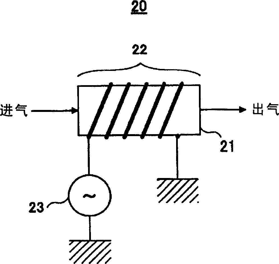
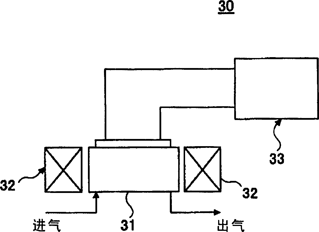
[0144] As previously explained, in the annular plasma generator, since the sputtering of the plasma to the wall of the plasma generator can be suppressed, the pollution in the substrate processing process using plasma is relatively small. Although there is such a preferable feature, Plasma ignition is difficult, so when plasma ignition is performed, it is necessary to remove the containing NF 3 Corrosion gas or purge gas of equal electronegative halide, and then ignited in the environment of 100% Ar gas.
[0145] Thus, conventionally, in the annular plasma generator, plasma ignition can only be performed in an atmosphere of 100% Ar gas. In view of this, the inventors of the present invention have the following ideas, that is: focusing on prolonging the mean free path (mean free path) of electrons under a reduced pressure environment, even in a ring plasma generating device, when it is l...
no. 2 example
[0159] As a second embodiment of the present invention, Figure 12 Shown are the results of the inventors of the present invention exploring the plasma ignition conditions at Figure 4 In the annular plasma generating device 60 shown, when various F 2 Concentration (F 2 / (Ar+F 2 )) to provide Ar and F to the gas passage 61 2 When the mixed gas is passed and the aforementioned Figure 9 carried out in the same order.
[0160] exist Figure 12 In the experiment, set the Ar / F 2 The flow rate of the mixed gas is 100SCCM, and a high frequency of 400kHz is provided with a power of 1300W.
[0161] refer to Figure 12 It can be known that when the entire gas flow rate is set to 100SCCM, the F in the mixed gas 2 When the concentration is 5%, plasma ignition occurs in the pressure range above about 6.65Pa (0.05Torr) and below 66.5Pa (0.5Torr). f 2 shrinks as the concentration increases, but until about 45% of the F 2 concentration can still be ignited.
no. 3 example
[0163] Thus, the inventors of the present invention succeeded in finding out in the basic research of the present invention that even in Figure 4 The annular plasma generating device shown provides Ar gas containing NF 3 or F 2 In the case of a mixed gas such as a highly electronegative halide gas, plasma ignition can also be performed, and the conditions under which plasma ignition can be performed have been successfully discovered.
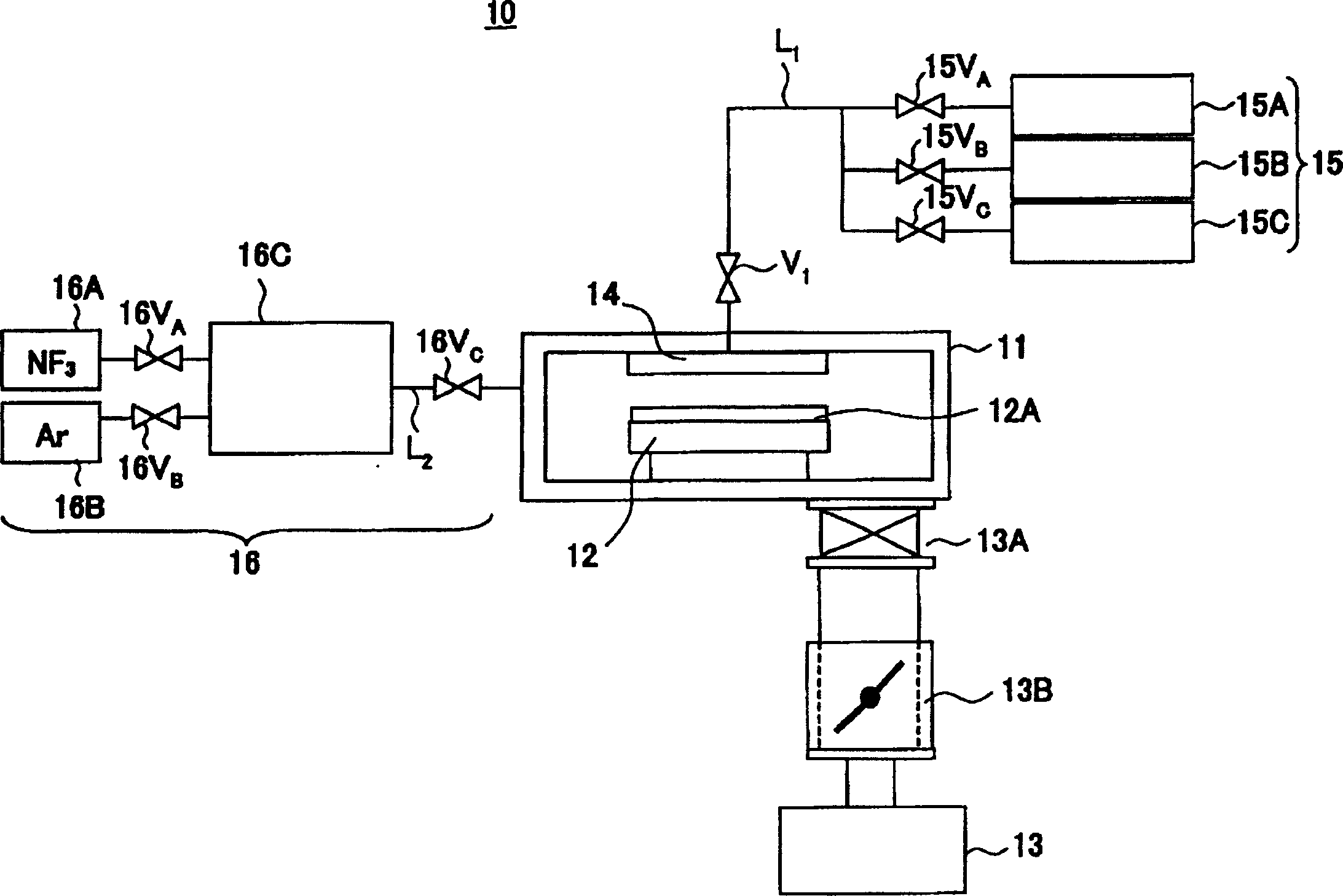
[0164] On the other hand, actually in a CVD apparatus, such as figure 1 The pressure or gas flow used for cleaning or etching in the CVD device 10 is much greater than Figure 9 or Figure 10 The ignition point shown, thus in the annular plasma generator 60, at Figure 9 or Figure 10 After the ignition point of the plasma is ignited, the plasma is not eliminated, but is required to change the conditions up to the processing point where the processing is actually performed. For example, according to the previously stated Figure 5 or I...
PUM
 Abstract
Description
Claims
Application Information
 - R&D
- Intellectual Property
- Life Sciences
- Materials
- Tech Scout
- Unparalleled Data Quality
- Higher Quality Content
- 60% Fewer Hallucinations
Browse by: Latest US Patents, China's latest patents, Technical Efficacy Thesaurus, Application Domain, Technology Topic, Popular Technical Reports.
© 2025 PatSnap. All rights reserved.Legal|Privacy policy|Modern Slavery Act Transparency Statement|Sitemap|About US| Contact US: help@patsnap.com


