Denitration of non-selective catalytic reducing smoke

A non-selective, denitrification technology, applied in chemical instruments and methods, dispersed particle separation, separation methods, etc., can solve the problems of reduced boiler thermal efficiency, increased exhaust heat loss, and increased production volume, reducing operating costs and reducing costs. The effect of flue gas denitration process

Inactive Publication Date: 2006-08-16
孙克勤 +3
View PDF0 Cites 9 Cited by
  • Summary
  • Abstract
  • Description
  • Claims
  • Application Information

AI Technical Summary

Problems solved by technology

But when a increases, more heat will be taken out of the furnace by the flue gas from the horizontal flue of the boiler, resulting in an

Method used


Image

  • Denitration of non-selective catalytic reducing smoke

Examples


Example Embodiment

[0014] The present invention will be further described below in conjunction with the accompanying drawings.

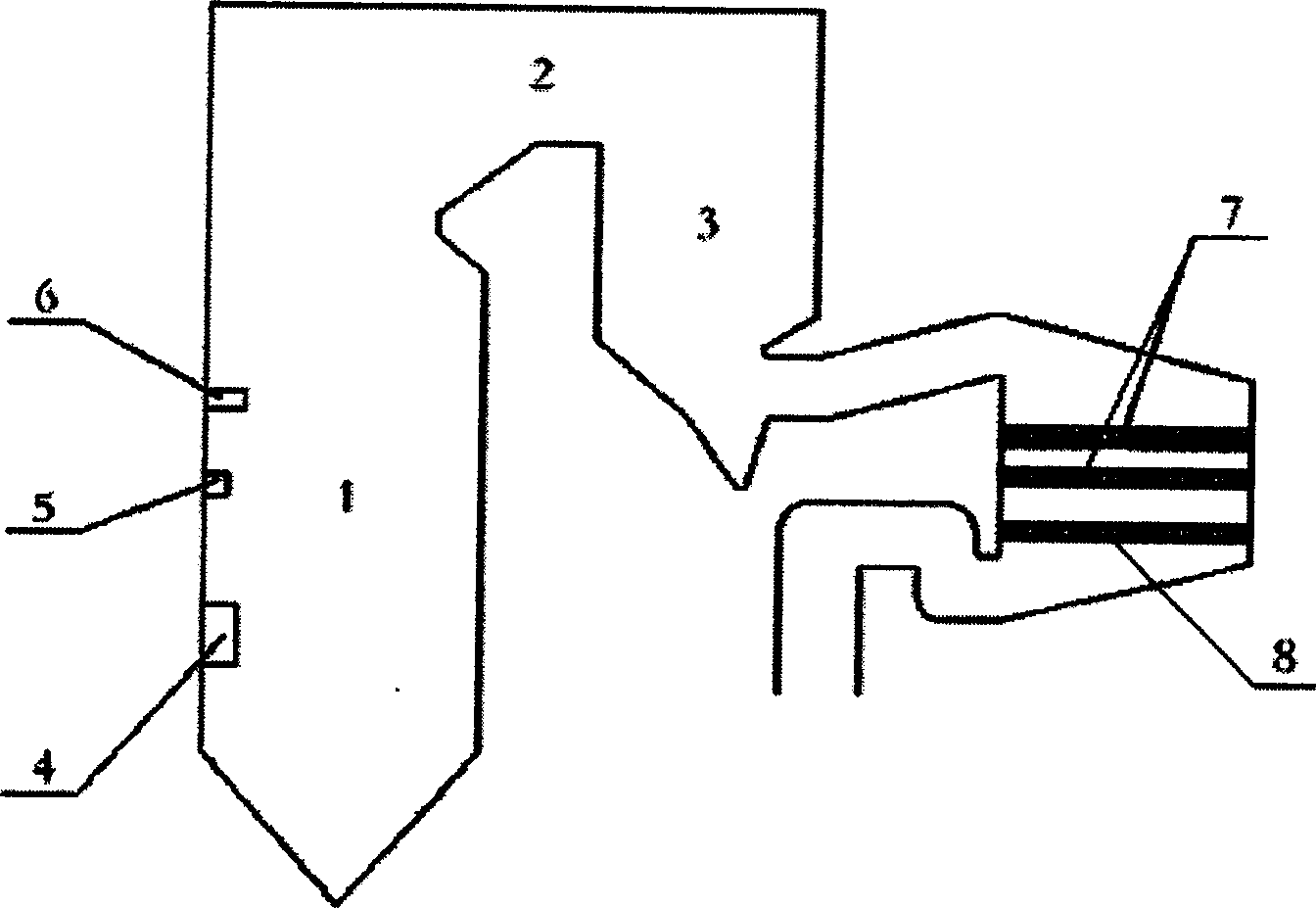
[0015] The denitrification device is composed of a boiler furnace 1, a horizontal flue 2, a tail flue 3, and a catalytic reactor 9 in series. The burner 4, the exhaust gas inlet 5, and the fine coal powder are arranged in the boiler furnace 1 from bottom to top. The injection port 6 is provided with 7 layers of NSCR catalyst and 8 layers of oxidation catalyst in the catalytic reactor 9 at the rear of the tail flue 3, and the oxidation catalyst 8 is arranged downstream of the NSCR catalyst 7. The fuel is burned in the boiler furnace 1, and 100% of the fuel required by the coal-fired unit is added at the position of the burner 4. At the same time, according to the specific coal type (mainly distinguished by volatile content), the equivalent air coefficient required for 0.75-85% of the fuel is added , The remaining air volume required for combustion is added at the overfire a...


PUM


Abstract

A non-selective catalytic reduction process for denitrating fume without spraying reducer includes such steps as controlling the excessive air coefficient of burner in boiler to 0.75-0.85, spraying burn-off air in it, regulating said excessive air coefficient to 1.05-1.15, spraying fine coal powder in it to obtain CO, H2 and hydrocarbon gas used as reducer, non-selective catalytic reduction reaction between NSCR catalyst and NOx in fume in the catalytic reactor, burning the residual CO gas under the action of oxidizing catalyst, and recovering its energy in preheater.

Description

technical field [0001] The invention relates to a catalytic reduction process for realizing flue gas denitrification without injecting a reducing agent, and belongs to the technical field of manufacturing and using environmental protection equipment. Background technique [0002] Nitrogen oxides (NO x ) is one of the main pollutants in the atmosphere, and its hazards mainly include acid rain, photochemical smog and other ways to endanger human health and ecological balance. while coal-fired power plants are NO x one of the main sources of pollution. In order to set NO x Emissions are controlled within a low range, and more and more coal-fired power plants use ammonia (NH 3 ) as the reducing agent to realize the selective catalytic reduction (SCR) process of flue gas denitrification. SCR is a high-efficiency flue gas denitrification process, but the SCR process usually uses NH 3 As a reducing agent, in the presence of a catalyst, with NO in the flue gas x Catalytic red...

Claims


Application Information

Patent Timeline
IPC IPC(8): B01D53/56B01D53/86
Inventor 孙克勤华玉龙
Owner 孙克勤
Why Eureka
Try Eureka