Thermoelectric conversion device, and cooling method and power generating method using the device

A thermoelectric conversion device and thermoelectric conversion technology, applied in the manufacture/processing of thermoelectric devices, thermoelectric devices, circuits, etc., can solve the problems of not reaching the thermoelectric conversion performance index, etc., and achieve the effect of excellent thermoelectric conversion performance

Active Publication Date: 2006-09-20
PANASONIC CORP
View PDF12 Cites 15 Cited by
  • Summary
  • Abstract
  • Description
  • Claims
  • Application Information

AI Technical Summary

Problems solved by technology

[0010] However, in the above-mentioned existing methods, the current situation is that among substances limited to the level of ZT > 1 as a practical standard, it is limited t

Method used


Image

  • Thermoelectric conversion device, and cooling method and power generating method using the device
  • Thermoelectric conversion device, and cooling method and power generating method using the device
  • Thermoelectric conversion device, and cooling method and power generating method using the device

Examples


Embodiment approach 1

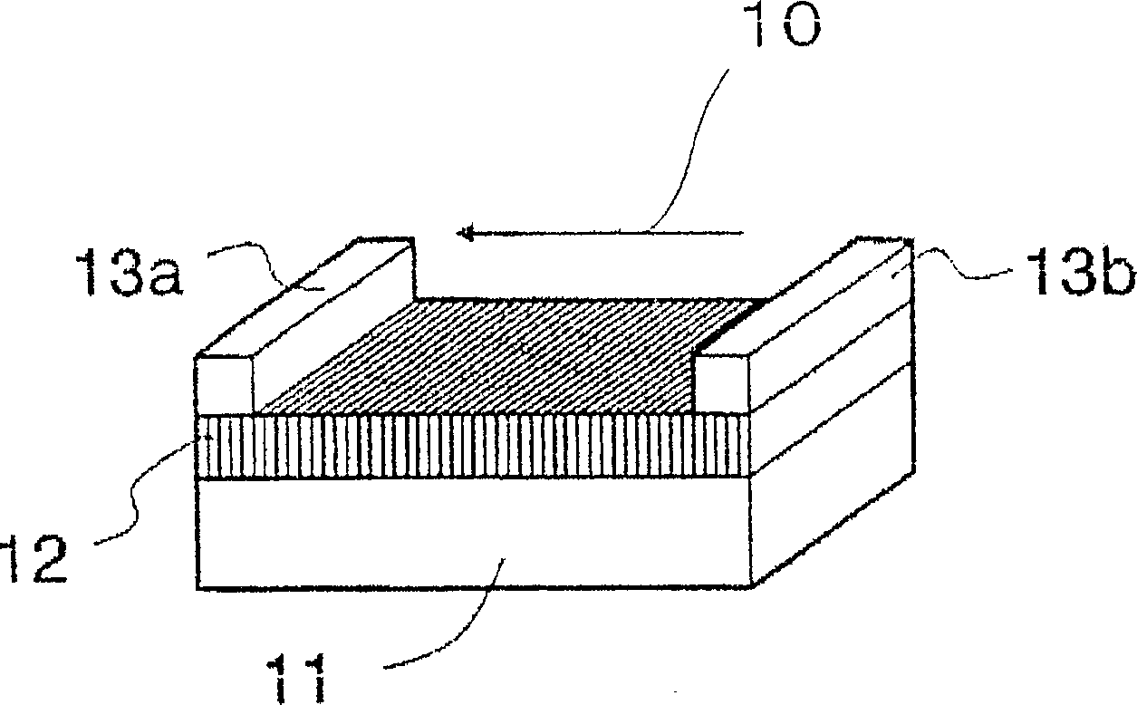
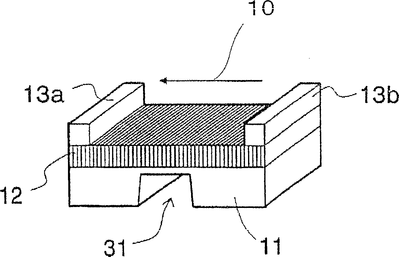
[0053] figure 1 The shown thermoelectric conversion device has: a plate-shaped base 11 ; a thermoelectric conversion film 12 on the base 11 ;

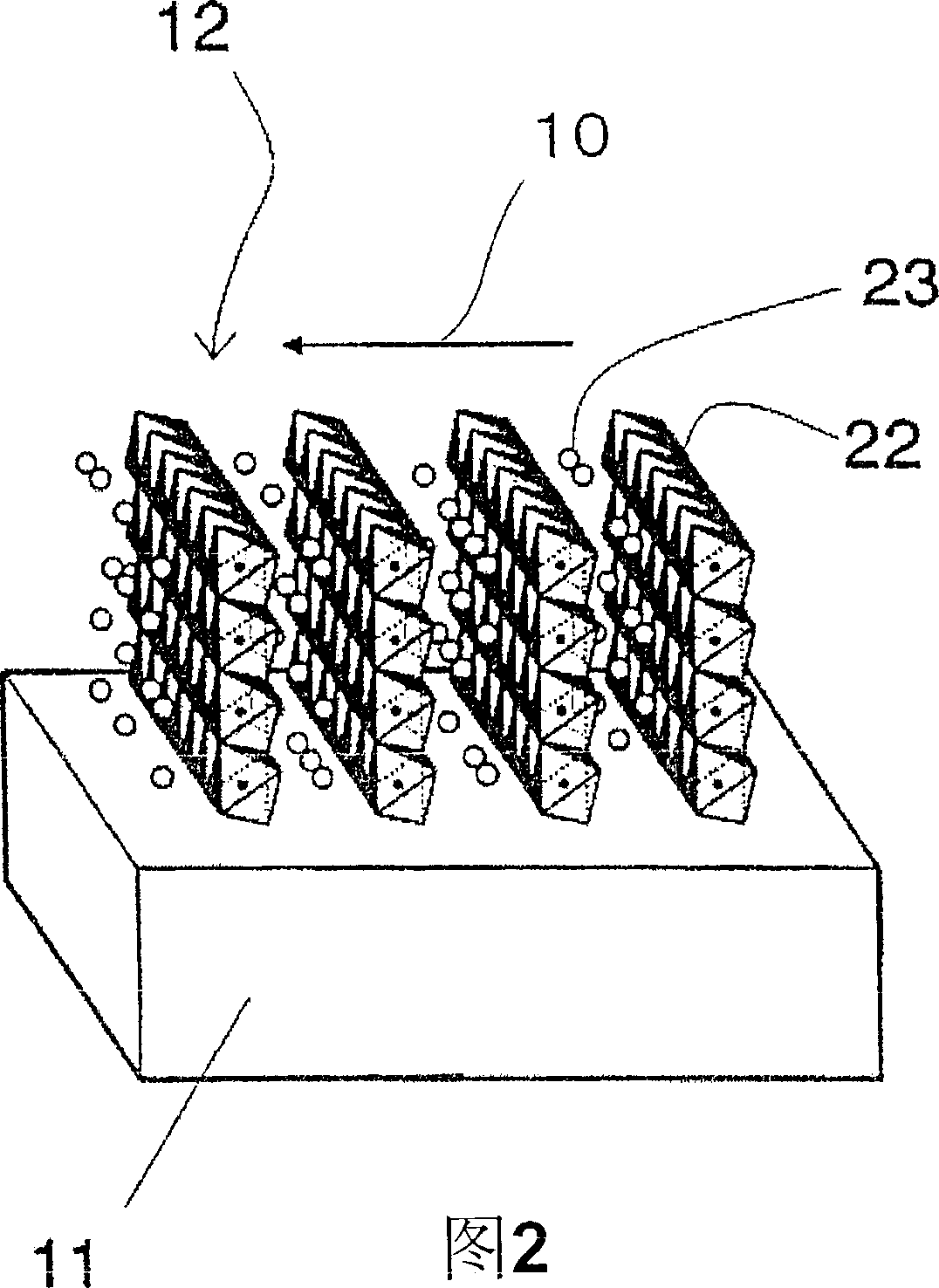
[0054] FIG. 2 illustrates the crystal structure of the thermoelectric conversion film 12 . The thermoelectric conversion film 12 has a layered structure in which electrically conductive layers 22 and electrically insulating layers 23 are alternately arranged. That is, the thermoelectric conversion film 12 is composed of a crystalline thin film in which electrically conductive layers 22 and electrically insulating layers 23 are alternately arranged.

[0055] In crystallography, the interlayer direction, that is, the direction perpendicular to the layer is called the c-axis direction 10 . A pair of electrodes 13 a , 13 b is arranged so that current can flow in the c-axis direction 10 .

[0056] The thermoelectric conversion film 12 is an epitaxial thin film (epitaxially grown film), and the c-axis direction 10 has orientation along th...

Embodiment 1

[0099] Sapphire Al of 10mm square and 100μm thick 2 o 3 On the A-side substrate, the layered oxide Na 0.4 CoO 2 film formation. The film formation method is to use a 4-inch diameter Na 0.5 CoO 2 RF magnetron sputtering of sintered targets.

[0100] 80% Ar, 20% O 2 The atmosphere was maintained at 5.0Pa, and after pre-sputtering was performed for 1 hour at an output power of 60W, deposition was performed on a substrate heated to 700°C for 5 hours under the same conditions as during pre-sputtering, and thereafter, the The thin film on the heated substrate was cooled to room temperature in an oxygen atmosphere for 2 hours, and as a result, a thin film having a film thickness of 1000 nm and having a metallic luster was obtained.

[0101] The composition ratio of Na and Co in the thin film was confirmed to be about Na:Co=0.4:1 by energy dispersive fluorescent X-ray analysis.

[0102] Na 0.4 CoO 2 The results of X-ray diffraction measurement of the film are shown in Figu...

Embodiment 2

[0117] used by CaO 2 、Co 3 o 4 A 4-inch raw material target (target) composed of a powder sintered body was grown on a 10 mm square, 100 μm thick sapphire M-plane substrate with a film thickness of 1000 nm under the same sputtering conditions as in Example 1.

[0118] It was confirmed by energy dispersive fluorescent X-ray analysis that the composition ratio of Ca and Co in the thin film was about Ca:Co=0.5:1. the Ca 0.5 CoO 2 The results of X-ray diffraction measurement of the film are shown in Figure 9 . In addition to the diffraction peak due to the sapphire substrate, only an index sub-peak based on (020) due to the diffraction of the thin film was observed.

[0119] It was thus confirmed that Ca 0.5 CoO 2 The film is epitaxially grown with the (010) plane parallel to the substrate. In addition, it was confirmed by 4-axis X-ray diffraction measurement that Ca 0.5 CoO 2 The c-axis of the crystals is oriented in-plane of the film.

[0120] Ca 0.5 CoO 2 The fil...


PUM

PropertyMeasurementUnit
Thicknessaaaaaaaaaa
Resistanceaaaaaaaaaa

Abstract

A thermoelectric conversion device having a high thermoelectric conversion performance. In the thermoelectric conversion device, electrodes are arranged unlike the arrangements steered by conventional technical knowledge so that current flows in the interlayer direction of a laminar material. A thermoelectric conversion film is epitaxially formed. An electrically conductive layer and an electric insulating layer are alternated. Each electrically conductive layer has an octahedron crystal structure in which a transition metal atom M is positioned at the center and oxygen atoms are positioned at the vertices. The electric insulating layer is made of a metal element or crystalline metal oxide. The c-axis of the laminar material of the electrically conductive layer and electric insulating layer is parallel to the in-plane direction of the base, and the pair of electrodes are arranged so that current flows along the c-axis.

Description

technical field [0001] The invention relates to a thermoelectric conversion device for mutual conversion of heat energy and electric energy by using Peltier effect and Seebeck effect. Background technique [0002] Seebeck effect, even when there is a temperature difference between the two ends of a substance, a thermoelectromotive force is generated according to the temperature difference. Thermoelectric power generation is a technology that uses the Seebeck effect to directly convert heat energy into electrical energy. It is formed by connecting an external load Close the circuit and be able to extract electricity. This technology has been applied to remote power supplies, space power supplies, and military power supplies. [0003] The Peltier effect is a phenomenon in which heat is transferred by electrons flowing with an electric current, and thermoelectric cooling is a technology utilizing the Peltier effect. Specifically, for example, two substances with different car...

Claims


Application Information

Patent Timeline
IPC IPC(8): H01L37/00H01L35/34
Inventor 四桥聪史菅野勉足立秀明小田川明弘杉田康成
Owner PANASONIC CORP
Why Eureka
Try Eureka