Synchro/rotary transformer-analog DC voltage transforming method

A technology of DC voltage conversion and resolver, applied in position/direction control, instruments, and electrical devices, etc., can solve the problems of inability to achieve high-density installation of system components, large interference, and reduced system reliability.

Active Publication Date: 2006-10-04
连云港杰瑞电子有限公司
View PDF0 Cites 13 Cited by
  • Summary
  • Abstract
  • Description
  • Claims
  • Application Information

AI Technical Summary

Problems solved by technology

[0006] 1. The precision is low. During D/A conversion, the signal and the error are amplified together by the analog amplifier, and the output voltage error is relatively large. At the same time, the separation element is used, which is greatly disturbed by external signals, the stability of the external reference is poor, and the output voltage accuracy

Method used


Image

  • Synchro/rotary transformer-analog DC voltage transforming method
  • Synchro/rotary transformer-analog DC voltage transforming method
  • Synchro/rotary transformer-analog DC voltage transforming method

Examples


Embodiment 1

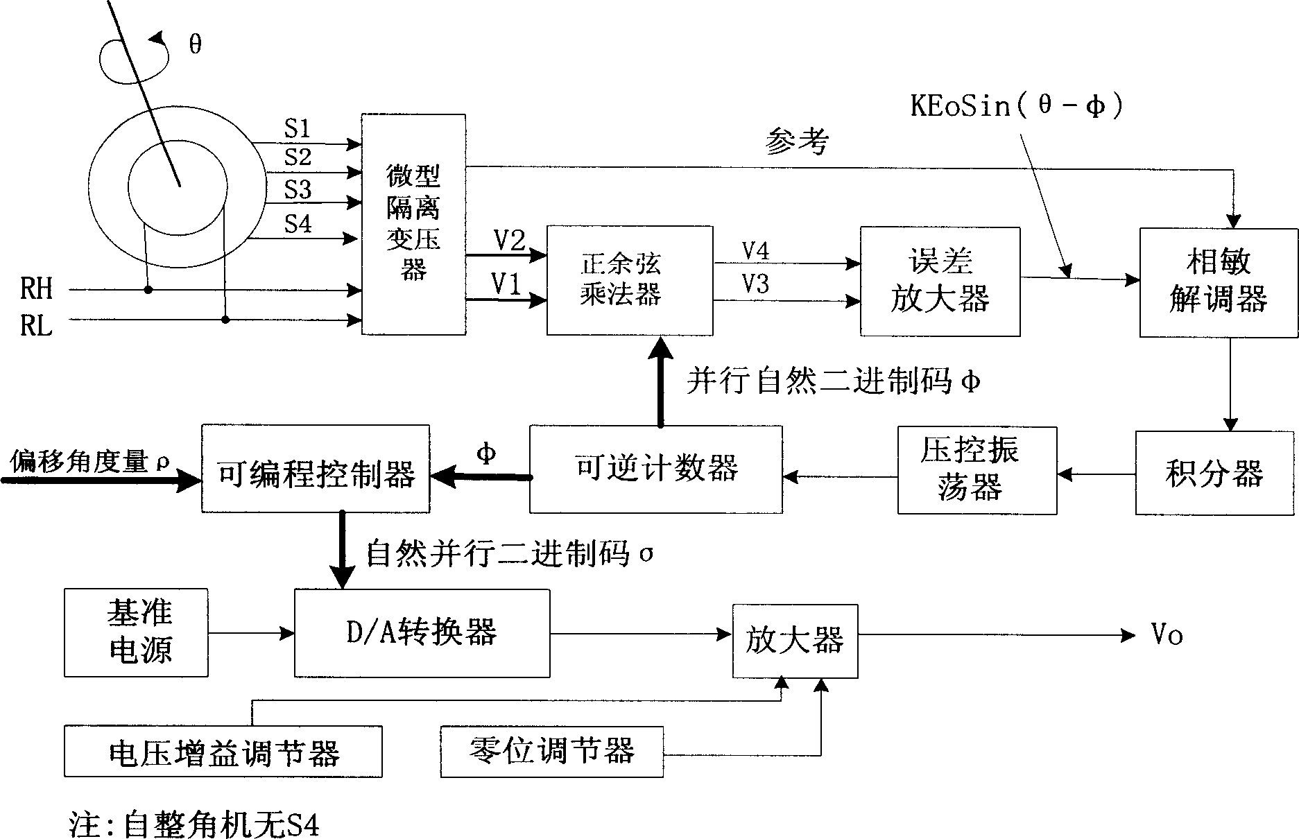
[0053] Example 1. refer to figure 1 . A synchro / resolver-analog DC voltage conversion method, characterized in that the synchro signal / resolver signal undergoes signal isolation transformation through a miniature isolation transformer to generate a set of sine and cosine signals V 1 and V 2 , multiplied with the digital angle φ generated by the reversible counter in the sine-cosine multiplier to obtain the signal V 3 , V 4 , output an error signal KEoSin(θ-φ) after passing through the error amplifier. When this process is completed, VSin(θ-φ)<1LSB, the auto-synchronizer / resolver shaft angle θ is converted into a digital angle φ output in the form of parallel natural binary code; the output digital angle φ is programmable by FPGA The controller performs digital amplification processing on the digital angle φ to increase or decrease the step size of the output digital angle to achieve signal amplification or reduction. The digital angle σ output by the FPGA programmable co...

Embodiment 2

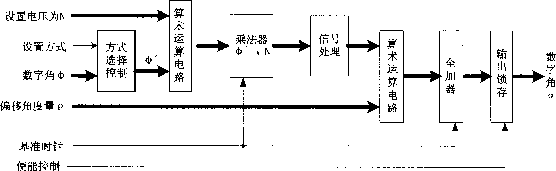
[0054] Example 2. refer to figure 1 , figure 2 , in Embodiment 1, in the FPGA programmable controller, the input digital angle φ signal is controlled by mode selection, so that the output digital angle φ' linearly increases or decreases linearly with the increase of the input angle φ, and the pipeline is realized by the arithmetic operation circuit After the technical design, the set output voltage and the input digital angle φ' carry out multiplier operation and signal processing, increase or decrease the step size of the output digital angle signal, and realize the amplification or reduction of the digital signal; the multiplier is set Controlled by a reference clock.

Embodiment 3

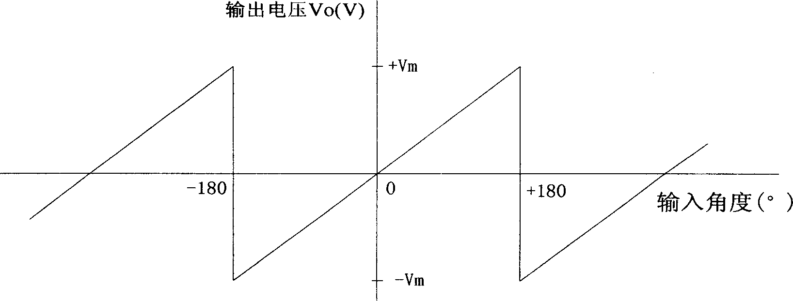
[0055] Example 3. refer to figure 1 , figure 2 , in embodiment 2, for the system that needs zero offset, the input offset angle ρ passes through the FPGA programmable controller, so that the offset angle ρ and the digital angle after signal processing are superimposed through the full adder, Realize the offset range of the zero point position between -180°-+180°, and complete the offset of the zero position signal. The full adder realizes the pipeline technology design through the arithmetic operation circuit; the enable control signal controls the output latch, so that the full The offset digital angle output of the adder is output or turned off; the full adder is provided with a reference clock for control.


PUM


Abstract

The analog dc voltage conversion method with synchro/resolver comprises: converting the axial angle of synchro/resolver into parallel natural binary O for output; amplifying the digital angle O with FPGA PLC to increase or decrease its output step for signal amplification or minification and output to a digital-analog dc voltage converter with a DAC, a reference power and a operational amplifier to complete the conversion. This invention has high reliability while low consumption.

Description

technical field [0001] The invention relates to a method for performing voltage processing on the synchro signal / resolver signal and directly converting the synchro signal / resolver signal into an analog DC voltage signal required for instrument control. Background technique [0002] The synchro is an induction electromechanical component, which is mainly used in automatic control, synchronous transmission and calculation solution system. It can transform the rotation angle of the rotating shaft into an electrical signal, or transform the electrical signal into the rotating angle of the rotating shaft, realize the long-distance transmission, reception and conversion of angle data, and achieve the purpose of automatically indicating angle, position, distance and command. [0003] A resolver is a signal element whose output voltage varies with the rotor angle. When the excitation winding is excited by an AC voltage of a certain frequency, the function r...

Claims


Application Information

Patent Timeline
IPC IPC(8): G01D5/14G08C19/16G01B7/30G05D3/00
Inventor 高文政程蜀炜夏伟张焱萍
Owner 连云港杰瑞电子有限公司
Why Eureka
Try Eureka