

Optical low-pass filter
A low-pass filter and optical technology, applied in optics, optical components, instruments, etc., can solve problems such as image quality degradation
- Summary
- Abstract
- Description
- Claims
- Application Information
AI Technical Summary
Problems solved by technology
Method used
Image

Examples
no. 1 Embodiment approach
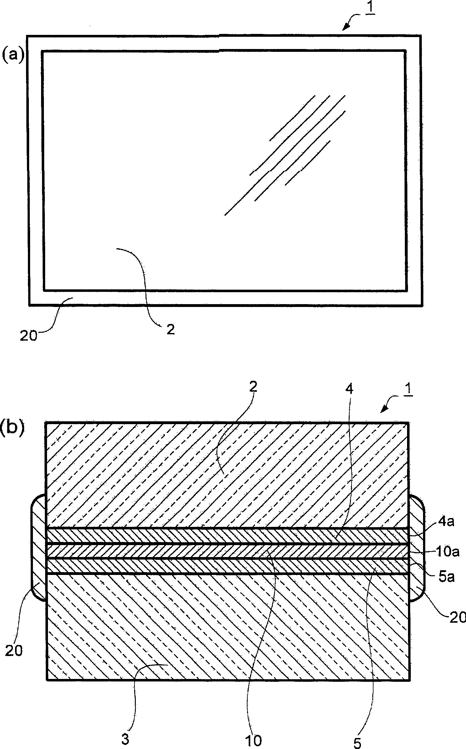
[0054] figure 1 (a) is a plan view of the optical low-pass filter 1 in the first embodiment, figure 1 (b) is a cross-sectional view of the optical low-pass filter 1 .
[0055] A retardation film 10 made of a polymer film as a 1 / 4 wavelength plate is pasted together with adhesive layers 4, 5 between the crystal plates 2, 3 as birefringent plates, and a sealing portion 20 is provided, so that at least The entire area including the outer periphery 4 a of the adhesive layer 4 , the outer periphery 5 a of the adhesive layer 5 , and the outer periphery 10 a of the retardation film 10 are covered.
[0056] The crystal plate 2 and the crystal plate 3 as the double refraction plate only need to be a crystal plate with birefringence, and besides the crystal, lithium niobate (LiNbO 3)Wait. It may be that only crystal plates are used for both plates, or a combination of crystal and lithium niobate or a combination of birefringent plates made of other materials may be used. Birefringen...
no. 2 Embodiment approach
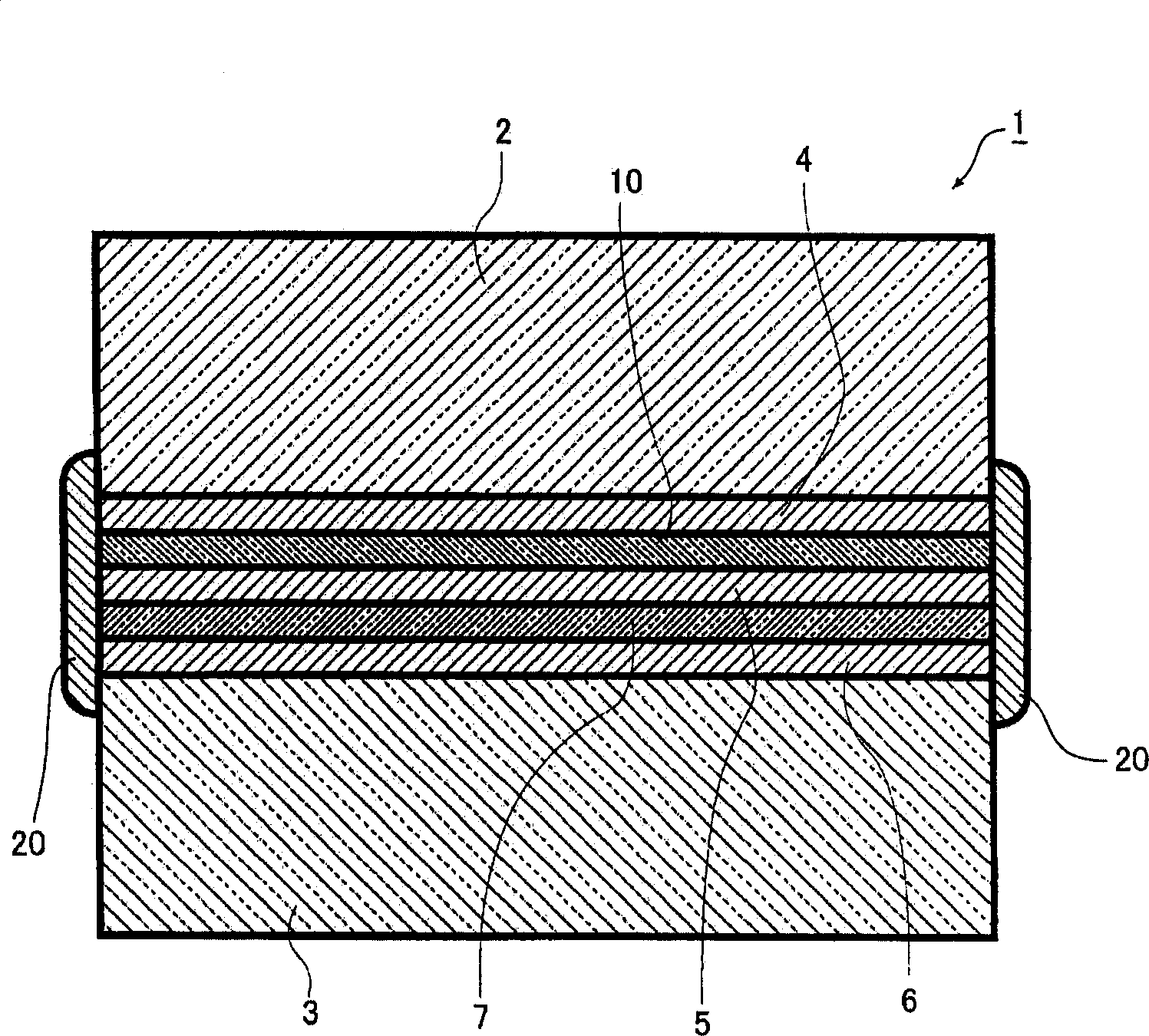
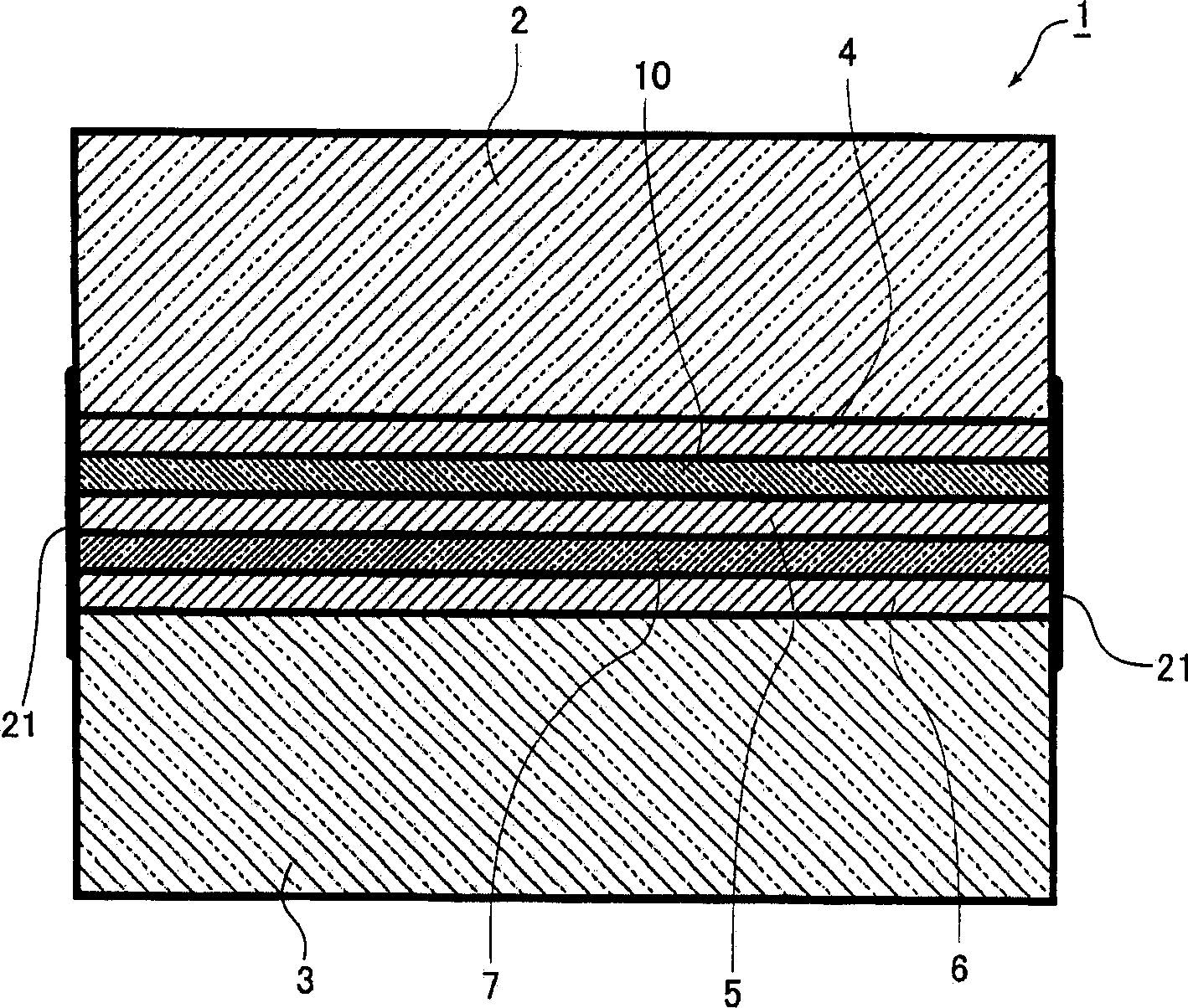
[0073] image 3 It is a cross-sectional view schematically showing the schematic configuration of the optical low-pass filter of the second embodiment. The basic structure of optical low-pass filter and figure 2 are basically the same, so the same symbols are used for the same parts and their descriptions are omitted. and figure 2 The optical low-pass filter shown is different in that a waterproof treatment part 21 is provided instead of the sealing part 20, and the waterproof treatment part 21 is the adhesive layer 4 in the outer peripheral surface of the optical low-pass filter treated with a waterproof treatment agent. , 5, 6 are formed by the exposed parts of the outer peripheries, covering the entire outer peripheries of these adhesive layers 4, 5, 6 and the phase difference film 10, and the entire outer peripheral surface of the infrared absorption filter plate 7. The waterproof treatment part 21 has covered the entire outer periphery of the adhesive layer 4, 5, 6 a...
no. 3 Embodiment approach
[0096] In the optical low-pass filter according to the third embodiment, at least a part of the outer periphery of the phase plate is located inside the outer periphery of at least one birefringent plate among the two birefringent plates, so that a step or a depression is formed. The step or depression forms the seal.
[0097] Figure 4 (a) is a plan view of the optical low-pass filter 1 in Example 1 of the third embodiment, Figure 4 (b) is a cross-sectional view of the optical low-pass filter 1 .
[0098] The crystal plate 2 serving as a birefringent plate is smaller than the crystal plate 3 serving as a birefringent plate. When the retardation film 10 made of a polymer film as a 1 / 4 wavelength plate is bonded together with the adhesives 4, 5, the crystal plate 2 is pasted on the inside of the crystal plate 3 so that the presence of the crystal plate 2 Steps 3a, 3b, 3c, 3d formed by different sizes from the crystal plate 3. Steps 3a, 3b, 3c, 3d may not be equal respectiv...
PUM
| Property | Measurement | Unit |
|---|---|---|
| Glass transition temperature | aaaaa | aaaaa |
| Film thickness | aaaaa | aaaaa |
Abstract
Description
Claims
Application Information