Earphone antenna connecting device and portable wireless device

An earphone antenna and connecting device technology, which is applied in the directions of earphone cable/cable storage, antenna equipment with additional functions, antennas, etc., can solve problems such as noise, and achieve the effects of reducing noise, increasing degrees of freedom, and improving noise characteristics

Inactive Publication Date: 2006-10-04
SONY CORP
View PDF3 Cites 9 Cited by
  • Summary
  • Abstract
  • Description
  • Claims
  • Application Information

AI Technical Summary

Problems solved by technology

[0005] However, in a portable wireless device equipped with an earphone antenna for mixed transmission of RF signals and low-frequency signals (audio signals) as described above, noise countermeasures at the connector portion where the earphone antenna is connected to the portable wireless device become a problem.
[0006] That is, RF signals are usually transmitted through a coaxial cable. However, in the connector part, since each transmission line is composed of contact elements, if an individual shielding structure is used for each transmission line, it will increase in size, and it is necessary to insert ferrite beads. and other countermeasures become constraints in the design of wireless equipment

Method used


Image

  • Earphone antenna connecting device and portable wireless device
  • Earphone antenna connecting device and portable wireless device
  • Earphone antenna connecting device and portable wireless device

Examples


Embodiment Construction

[0024] Hereinafter, embodiments of the present invention will be described in detail with reference to the drawings. In addition, it is needless to say that the present invention is not limited to the following examples, and can be changed arbitrarily within a range not departing from the gist of the present invention.

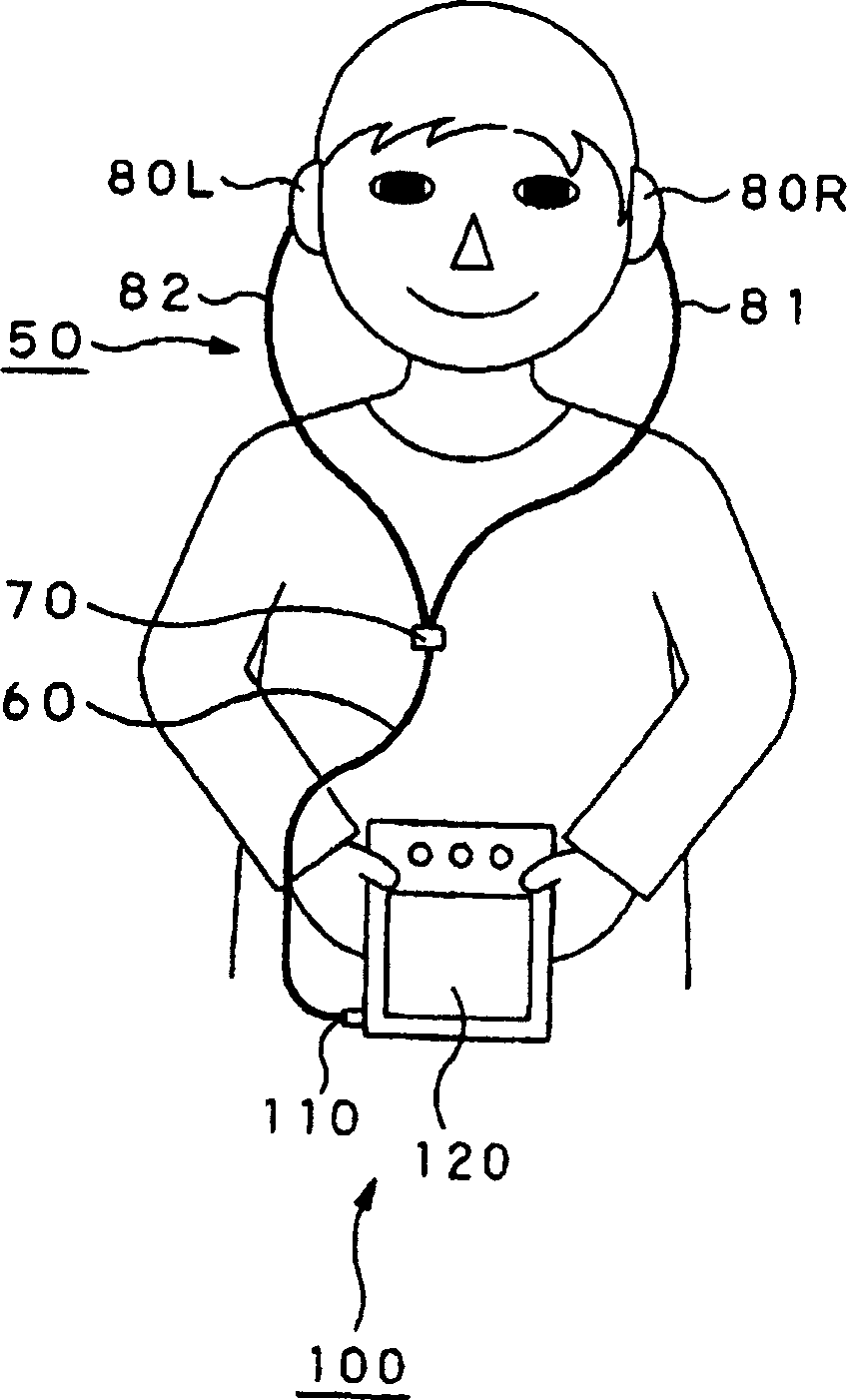
[0025] The present invention applies to, for example figure 1 In the liquid crystal television receiver 100 of the structure shown.

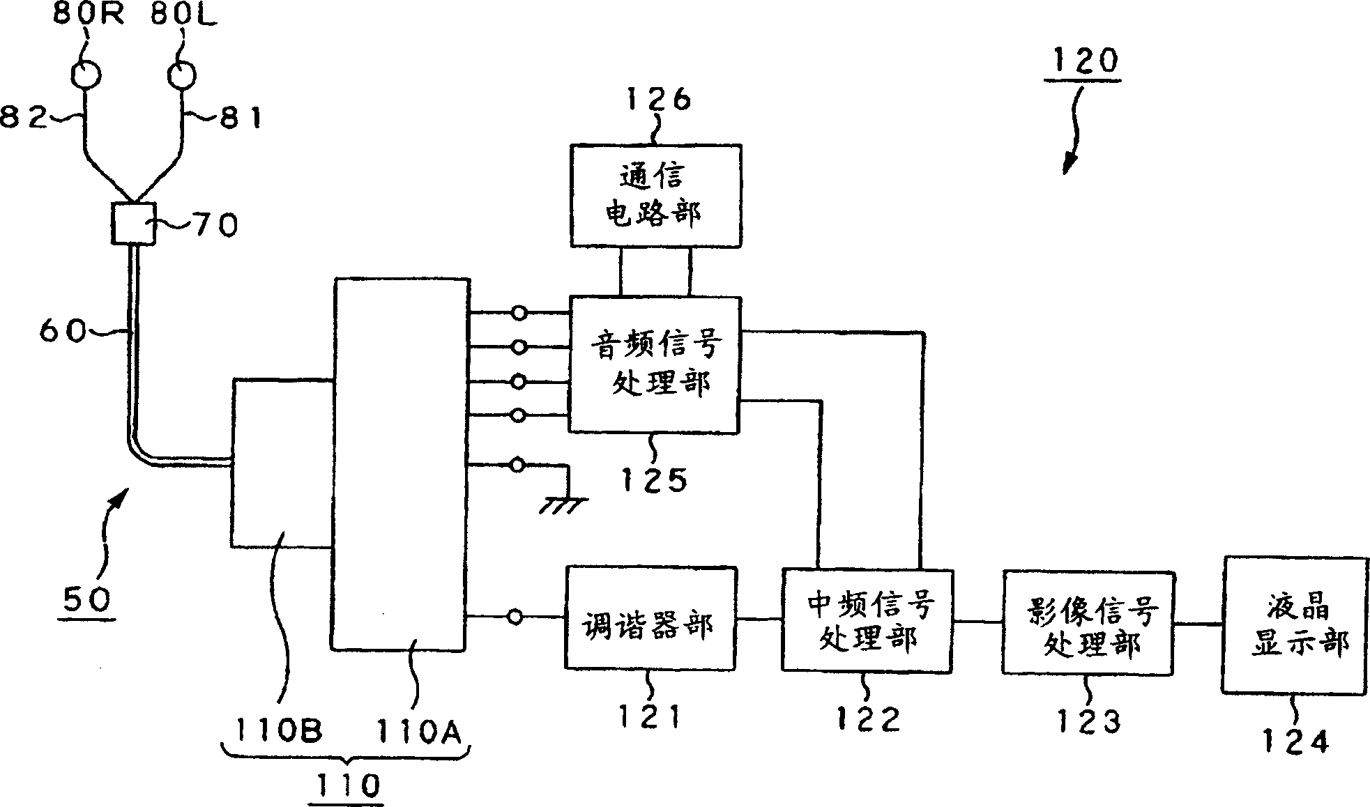
[0026] Should figure 1 The illustrated liquid crystal television receiver 100 is equipped with an earphone antenna 50 connected to the receiver main body 120 through a pin plug connector 110, transmits a television signal received through the earphone antenna 50 to the receiver main body 120, and passes through the receiver main body 120. The earphone antenna 50 transmits audio signals to the stereo earphones 80L, 80R.

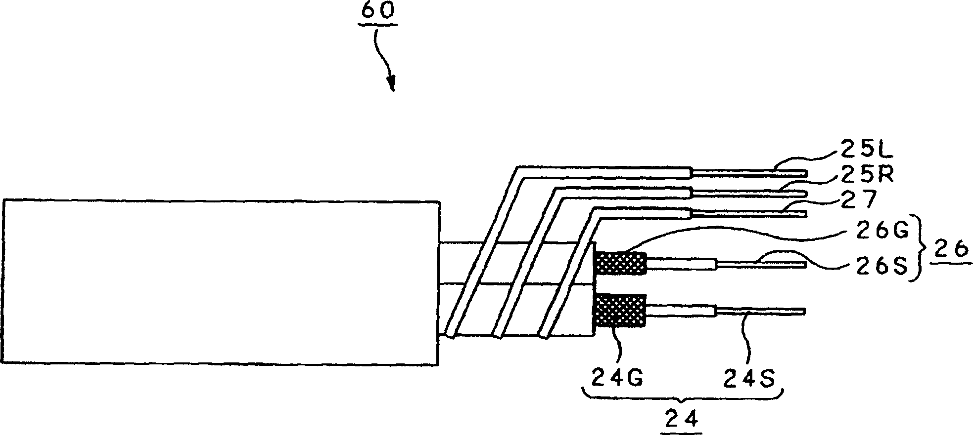
[0027] The earphone antenna 50 includes: a coaxial cable 60, one end of which is connected to the above-me...


PUM


Abstract

A coaxial cable (60) is used for transmitting a low frequency signal and an RF signal to a receiver main body (120). At the time of using an earphone antenna connecting device by soldering it to pins of a pin plug connector (110) used for connecting with the coaxial cable, a conversion board is provided for pins (11~ 20) of a 10 pin plug connector (115), and a rear plane of a pattern of the conversion board is used for grounding, except a pin inserting slot (100) of the pin (20) connected with an antenna signal line (9). Pin inserting slots (134A, 135A, 132A) into which audio signal pins (14, 15) and a microphone pin (12) for transmitting low frequency waves such as voice are surrounded from at least three sides. Thus, noise in devices from a voice signal and a microphone signal is reduced, high frequency signal transmission characteristics are improved by the connector, and the degree of freedom in board layout is improved.

Description

technical field [0001] The invention relates to an earphone antenna connection device and a portable wireless device for mixed transmission of RF signals and low frequency signals. [0002] This application claims priority based on Japanese Patent Application No. 2004-202322 filed on July 8, 2004 in Japan, and this application is referred to in this application. Background technique [0003] Conventionally, for example, as shown in JP-A-2003-163529, portable wireless devices such as pagers, radios, and liquid crystal television receivers worn on the human body use whip antennas or devices that transmit audio signals to earphones. The signal line is used as the antenna of the earphone antenna (earphone antenna). [0004] In addition, in the case of connecting an antenna having a coaxial line, for example, as disclosed in JP-A-9-199237, etc., a dedicated connector is used to remove the noise loaded in the audio signal of the headphone by Insert a ferrite ...

Claims


Application Information

Patent Timeline
Patent Type & Authority Applications(China)
IPC IPC(8): H04R1/10H05K1/02
CPCH01Q9/16H05K1/0218H01Q1/273H04R1/1033H05K2201/09318H05K3/3447H05K2201/0715H04R2420/07H01Q1/46H04R1/10H05K1/02
Inventor 吉野功高
Owner SONY CORP
Why Eureka
Try Eureka