
Modularized stator structure low-speed DC brushless motor

A DC brushless, fixed stator technology, applied in the direction of magnetic circuit shape/style/structure, electrical components, electromechanical devices, etc., can solve the problems of small stator winding coefficient, reduction of permeance torque of permanent magnet teeth, reduction of motor efficiency, etc. , to achieve simple winding process, reduce permanent magnet permeance harmonic torque, and high motor efficiency

Inactive Publication Date: 2006-11-15
TIANJIN UNIV
View PDF0 Cites 12 Cited by
  • Summary
  • Abstract
  • Description
  • Claims
  • Application Information

AI Technical Summary

Problems solved by technology

The ends of the DC brushless motor windings with the traditional stator structure overlap each other and the ends are longer. At the same time, in order to reduce the permeance torque of the permanent magnet teeth, the stator slots are usually inclined by one stator tooth pitch, and the basic electromagnetic torque that the motor can output is reduced. Reduced motor efficiency
However, although the stator of a general modular permanent magnet synchronous motor does not use inclined slots, but uses fractional slots, the ends of the windings do not overlap each other, and the ends are relatively short, but the stator winding coefficient is relatively small, which affects the power index and efficiency of the motor.

Method used


Image

  • Modularized stator structure low-speed DC brushless motor
  • Modularized stator structure low-speed DC brushless motor
  • Modularized stator structure low-speed DC brushless motor

Examples


Embodiment Construction

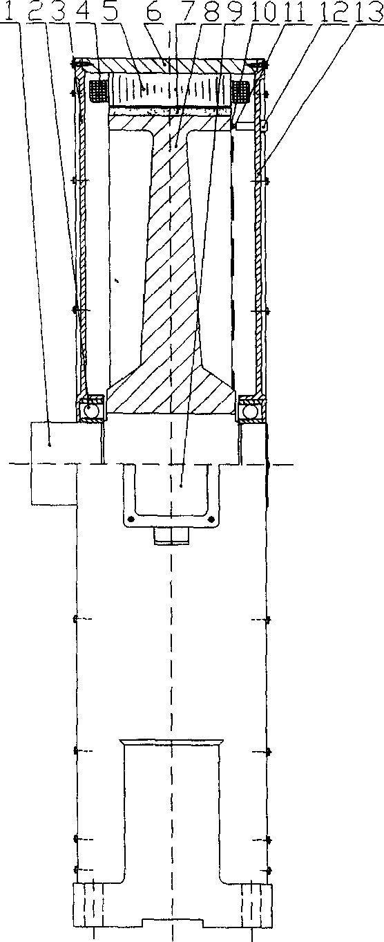
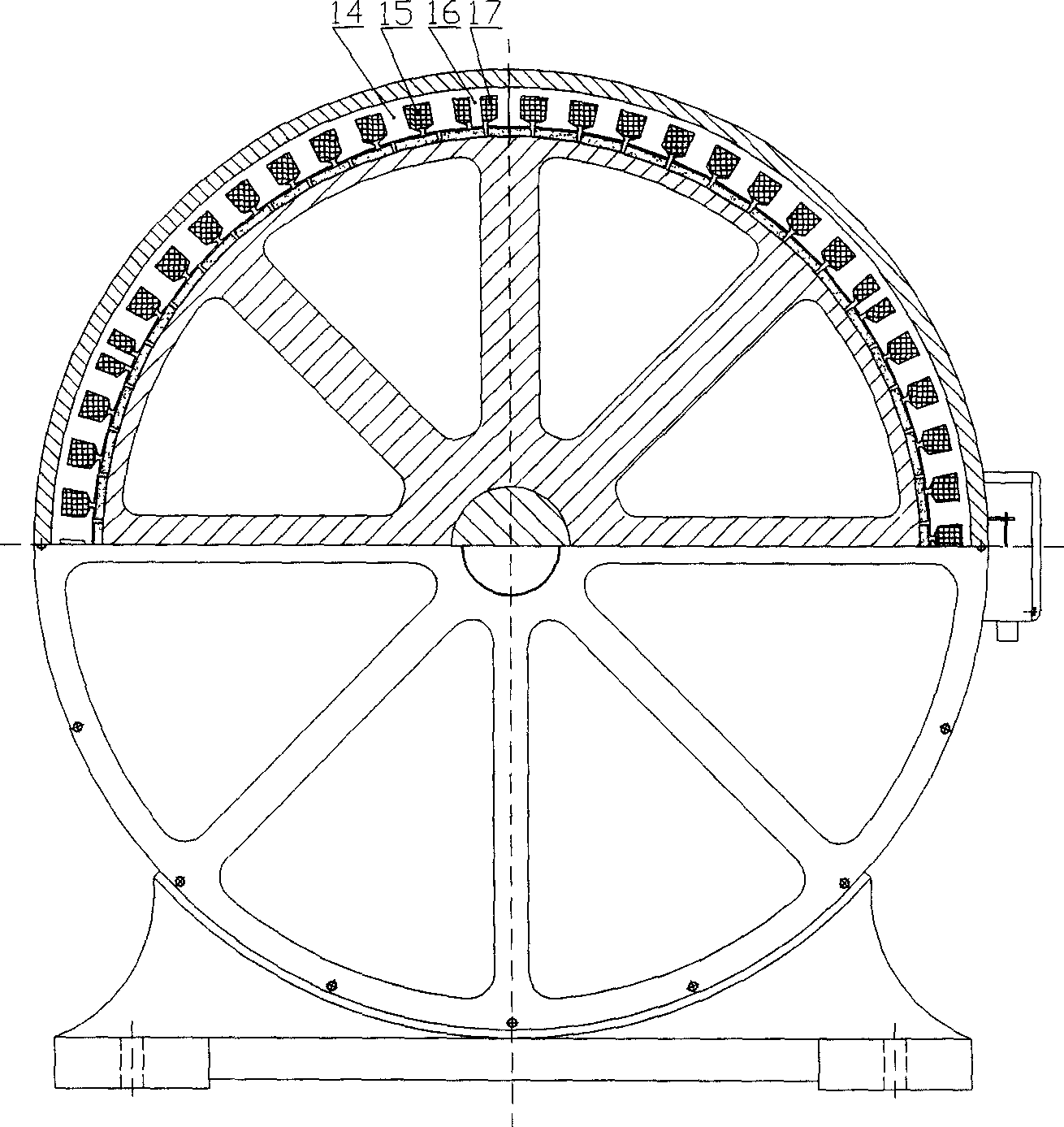
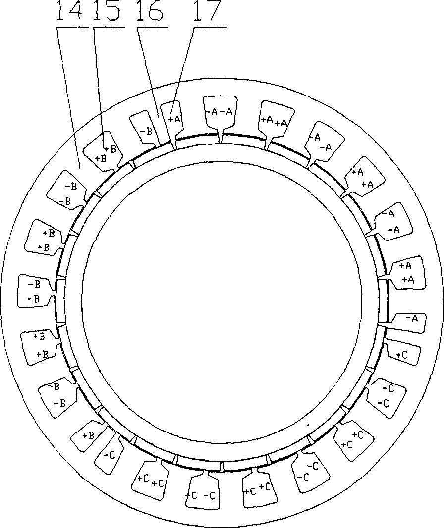
[0010] like figure 1 , 2 Shown is a schematic diagram of the structure of a low-speed brushless DC motor with a modular stator structure of the present invention. The motor includes a frame 6, front 3 on both sides of the frame, a rear end cover 13, a rotor shaft 1, a junction box 9, a position sensor, and a position sensor. Sensor junction box 12, Y-connected three-phase winding, modular stator core 5 fixed in the base, rotor installed on the rotor shaft, main magnetic pole NdFeB permanent magnets are arranged on the circumference of the rotor 7. Divide the inner diameter of the stator core evenly into k 1 Sector group, in each sector group A, B, C three-phase each occupying one sector with the same area, one sector belongs to one phase, and the stator core of each sector is evenly opened with k 2 A large tooth 15, a large slot 14 is arranged between the two adjacent large teeth, the tooth pitch of the adjacent large teeth is a pole pitch, and the distance between the two a...


PUM


Abstract

The invention discloses the blocking stator structure low speed direct current brushless motor. It divides evenly the inner diameter circle of the stator iron core into the K1 fan section group, the A, B, C three phases of each fan section group accounts for the same superficial one fan section respectively, the stator iron core of each fan section are mounted with K2 canine tooth, the tooth distance between the border canine tooth is one polar distance, the stator iron core between the said border two fan sections are mounted with one the small slot respectively, one small tooth is mounted between the said two small slots, the settling distance collecting loop are coiled on each canine tooth, the poles of the electric machine of the invention can be designed largely, the ends of the electric machine stator winding don't fold each other, the ends are shorter, the winding modulus is one, the process of the coiling is easy, and the stator iron core of the electric machine can depress the permanent magnet guiding humorous wave torque availably without the flume, the efficiency of the electric machine is high.

Description

technical field [0001] The invention relates to a low-speed DC brushless motor, in particular to a low-speed DC brushless motor with a modular stator structure. Background technique [0002] Low-speed DC brushless motors should be able to output high torque at low speeds and run stably. This requires a large number of pole pairs of the motor, and at the same time, a flat structure is selected to enable the motor to generate larger torque and lower speed under a certain armature volume and armature voltage. The ends of the DC brushless motor windings with the traditional stator structure overlap each other and the ends are longer. At the same time, in order to reduce the permeance torque of the permanent magnet teeth, the stator slots are usually inclined by one stator tooth pitch, and the basic electromagnetic torque that the motor can output is reduced. Reduced motor efficiency. However, although the stator of the general modular permanent magnet synchronous motor does no...

Claims


Application Information

Patent Timeline
IPC IPC(8): H02K29/06H02K1/12H02K1/27H02K29/08
Inventor 陈益广沈勇环王晓远
Owner TIANJIN UNIV
Learn More