Unit test system and method for automatic generating stub and driving function

A driving function, automatic generation technology, applied in software testing/debugging and other directions, can solve the problems of limited use, large workload, low degree of automation, etc., to improve reusability and flexibility, improve efficiency and quality, The effect of reducing skill requirements

Inactive Publication Date: 2006-12-06
BEIJING YUANXIN SCI & TECH
View PDF1 Cites 38 Cited by
  • Summary
  • Abstract
  • Description
  • Claims
  • Application Information

AI Technical Summary

Problems solved by technology

This method needs to construct stub functions and global variables, so the workload is heavy, and the reusability of the test code is poor
[0006] The second stage: with the help of white box testing open source code tools: CppUnit is the most common white box testing open source code, through the method provided by CppUnit to construct stubs and global variables, it is necessary to compile and execute CppUnit together with the program under test, this method Software test automation is not realized, and the CppUnit code is required to be compiled in the target environment, which requires a large change to the program under test
[0009] Among the patents of automatic unit testing, US2004153830 (Method and system for object level software testing) published on August 5, 2004 is the same as the above-mentioned automatic testing tool method in the third stage, but these unit testing methods do not have stubs and The automatic generation of the driver function inevitably requires the user to understand the call and execution logic of the function under test. It is necessary to use a script or a certain language to control the test logic, which increases the skill requirements of the testers, and the user needs to spend a certain amount of time learning these testing method
In addition, due to the powerful functions of these general unit testing tools, the degree of automation is not high in specific environments, which limits their wide use in some specific environments.

Method used


Image

  • Unit test system and method for automatic generating stub and driving function
  • Unit test system and method for automatic generating stub and driving function
  • Unit test system and method for automatic generating stub and driving function

Examples


Embodiment Construction

[0039] In order to make the purpose, technology and advantages of the present invention clearer, the present invention will be further described in detail below in conjunction with the accompanying drawings.

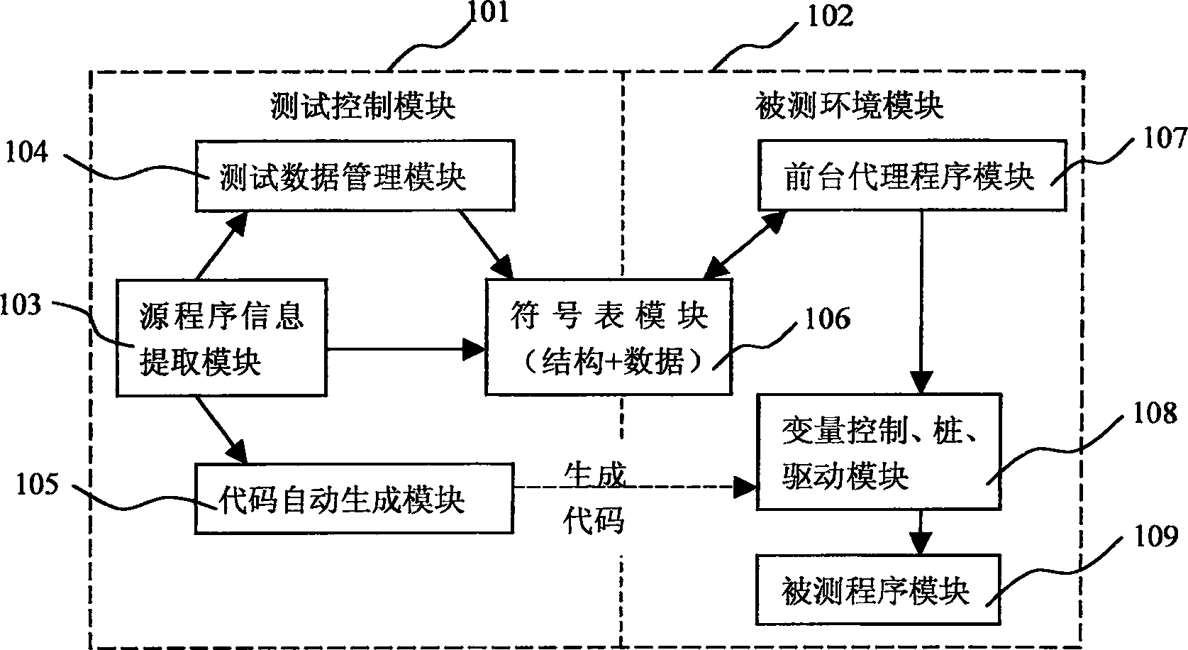
[0040] figure 1 A schematic diagram of the module structure according to the present invention is shown, illustrating the main module structure in the present invention.

[0041] The present invention can be generally divided into two parts, the test control module 101 and the tested environment module 102. The test control module 101 is used to complete the creation and execution control of the test cases, and is responsible for the interactive interface with the user; The software and hardware environment required for the dynamic execution of the test program is responsible for the interaction with the test control and controls the correct execution of the program under test. The use of these two independent parts will not increase the complexity of the system because...


PUM


Abstract

The invention discloses a software automatic test system and the method of automatically production variable control function, the pile function, the driving function. This method scans source program on test condition,and obtains this source program the information structure, and saves the information for XML document; as well as, based on the XML document information, automatically produce variable control function, the pile function, the driving function; the test control module controls the test program on test condition. The method can improve the software element testing efficiency.

Description

technical field [0001] The invention relates to a software automatic testing technology, more specifically an automatic testing method in which a system generates a variable control function, a stub function and a driving function according to the code of the tested software and a system using the method. Background technique [0002] Unit testing is to test each program unit in the program source code one by one to check each control branch and find errors as much as possible. [0003] The key to unit testing is to build a testing environment, in which driver functions and stub functions are often used. The driving function is used to call the function in the program under test, and the stub function is to provide a replacement function when the function in the program under test calls the sub-function. [0004] The level of unit testing in current software development is uneven, and can be generally divided into the following three stages: [0005] The first stage: pure ...

Claims


Application Information

Patent Timeline
Patent Type & Authority Applications(China)
IPC IPC(8): G06F11/36
Inventor 高旭涛马军尤培刚肖遂
Owner BEIJING YUANXIN SCI & TECH
Why Eureka
Try Eureka