
Method and system for monitoring continuous exhaust of smoke

A monitoring system and flue gas emission technology, which are applied in measurement devices, color/spectral characteristic measurement, and analysis using electron paramagnetic resonance, etc., can solve the problem of increased failure probability, increased maintenance workload, and large maintenance workload and other problems, to achieve the effect of reducing the measurement delay time, saving the heat tracing pipeline, and reducing the maintenance workload.

Active Publication Date: 2006-12-27
FOCUSED PHOTONICS
View PDF0 Cites 15 Cited by
  • Summary
  • Abstract
  • Description
  • Claims
  • Application Information

AI Technical Summary

Problems solved by technology

However, this type of system also has the following disadvantages: 1) The measurement time delay is relatively large, because it is necessary to pass the flue gas in the measured pipeline to the measurement pool through a long heating pipeline for measurement, resulting in a relatively large time delay; Reducing the delay time requires the use of a large-flow air pump, but this solution increases the load on the pretreatment system while speeding up the response time, such as causing the sampling device to be easily blocked, and the condenser load to become larger and prone to failure; 2) The cost is high. On the one hand, the unit price of the heating pipeline is high, and a long heating pipeline is usually required; on the other hand, the sampling device, the heating pipeline and the measuring cell all need independent temperature control devices; 3) Measurement The error is large, and the flue gas needs to be transported to the heating measurement pool through a long heating line, but the long heating line may have uneven heating, which leads to the phenomenon that the heating line is not heated locally. During the transmission process, the components in the flue gas Distortion may occur, resulting in inaccurate measurement; 4) The possibility of failure increases, and the uneven heating that may exist in the long heating pipeline will cause the pipeline to freeze and rupture at low ambient temperature; 5) It is inconvenient to install and maintain, and the long heating pipeline needs to be replaced An analysis system where the pipeline leads from the height of the measured chimney to the ground
Although this system avoids the use of heat tracing pipelines, it still has the following disadvantages: 1) calibration is troublesome, and usually the measuring probe of the monitoring system installed in the chimney height under test needs to be removed from the chimney under test before calibration, because National and industry standards require regular calibration of the flue gas emission continuous monitoring system, which brings great inconvenience to users; 2) The scalability of this type of monitoring system is poor, and the type of gas to be measured is limited by the monitoring system. For example, the ultraviolet differential method cannot measure carbon monoxide and carbon dioxide. At this time, a new monitoring system needs to be added to analyze these gas types; Harsh, high temperature, much dust, large airflow fluctuations, etc. These factors reduce the accuracy of measurement; 4) The maintenance workload is heavy, because the measurement probe needs to be inserted into the measured pipeline, the measurement probe is easily corroded by some corrosive gases, At the same time, the dust and tar in the gas will also pollute the light reflection device, and the optical components need to be cleaned regularly, which increases the maintenance workload

Method used


Image

  • Method and system for monitoring continuous exhaust of smoke
  • Method and system for monitoring continuous exhaust of smoke
  • Method and system for monitoring continuous exhaust of smoke

Examples


no. 1 example

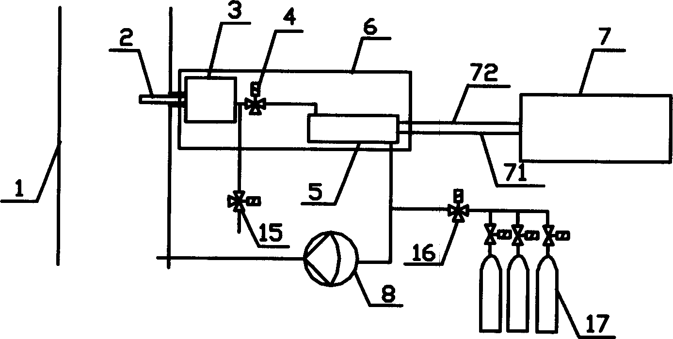
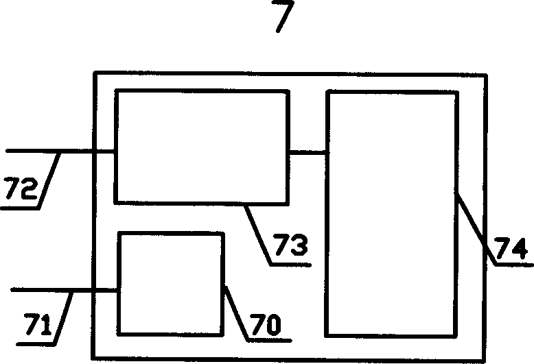
[0025] like figure 1 , image 3 As shown, a continuous monitoring system for flue gas emission includes a sampling probe 2, a heating device 6, a first measuring device, an air extraction pump 8, a standard gas cylinder 17 and valves 4, 15, 16. The sampling probe 2 is installed on the measured pipeline 1 and connected with the heating device 6 . The heating device 6 is equipped with a pretreatment device 3 such as a filter, a valve 4 and a measuring pool 5, and the preprocessing device 3 is connected to the valve 4 and the measuring pool 5 in sequence. An electric heating plate (not shown) is installed on the outer edge of the heating device 6, so that the pretreatment device 3 and the measuring cell 5 are heated together, so that the gaseous components in the heated measuring cell 5 are very close to the components in the measured pipeline 1 . The valve 15 is installed on the gas pipe behind the pretreatment device 3 , and the valve 16 and the standard gas bottle 17 are in...

no. 2 example

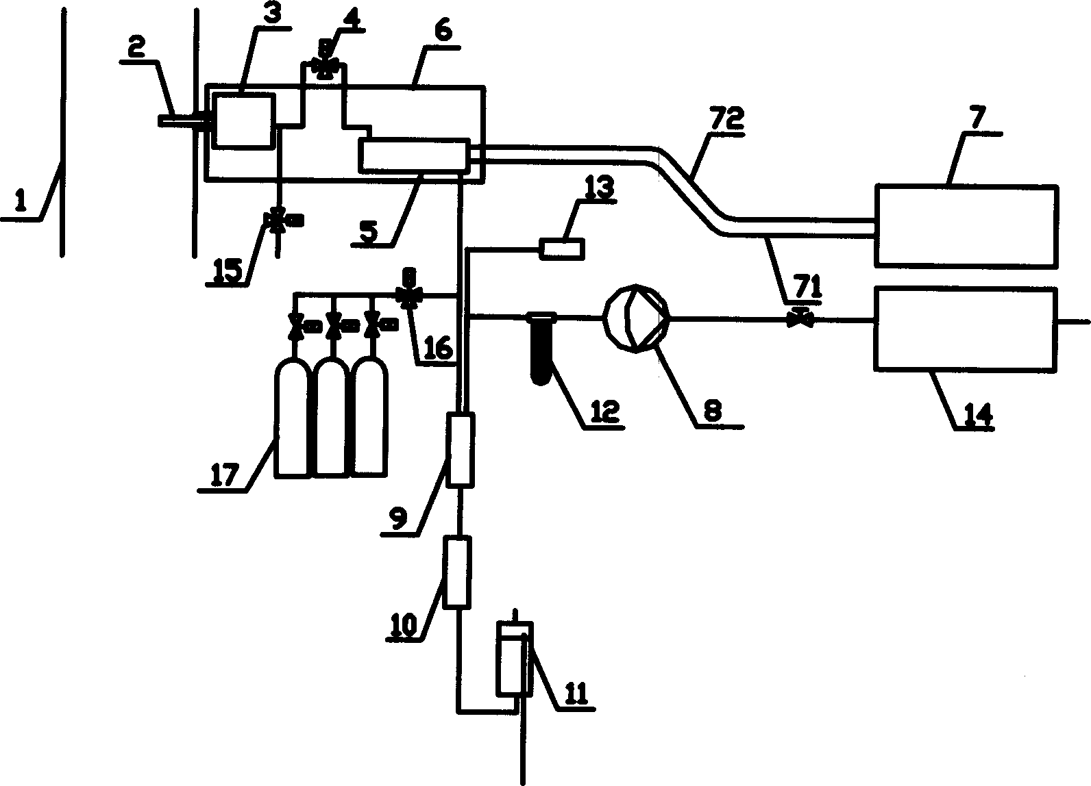
[0031] like figure 2 , Figure 4 As shown, a continuous monitoring system for flue gas emission is different from the first embodiment in that no humidity sensor and pressure sensor are installed on the heating measuring pool 5 . Heating plates are no longer installed on the outer edge of the heating device 6, but heating elements (not shown) are respectively installed on the outer edges of the pretreatment device 3 and the measurement pool 5, so that the pretreatment device 3 and the measurement pool 5 can be kept at different temperatures . The flue gas to be measured is discharged from the pretreatment device 3, such as a filter, and passes through the air pipe to the heating measurement pool 5. A part of the air pipe is exposed outside the heating device 6, and a valve 4 is installed on the exposed part of the air pipe. The monitoring system also includes a water removal device, a second measuring device, and the heating measuring pool 5 is connected to the water remova...


PUM


Abstract

The invention relates to a method for continuously detecting the smoke discharge, which comprises: a, the smoke of tube is sampled by the sampling detector; b, the sample smoke is fed into heater, to be preheated and fed into the heating measure pool; c, using spectrum analyze technique to measure the density of at least one tested gas or the material which is gas when heated but not gas in normal temperature in the pool. The invention also discloses a relative detecting system. The invention has low error, low cost, and high response speed.

Description

technical field [0001] The invention relates to the field of continuous monitoring of flue gas, in particular to a method and system for continuous monitoring of flue gas emission. Background technique [0002] The flue gas emission continuous monitoring system is a system for monitoring the pollution sources of flue gas emission. An existing continuous monitoring system for flue gas emission comprises a heating sampling device, a heating pipeline, a heating measuring pool and a measuring device. The heating sampling device is generally installed in the middle or higher of the measured chimney, etc., and the position is higher. After the flue gas in the measured chimney is sampled and filtered by the heating sampling device, it is passed to the heating measurement pool on the ground through the whole heating pipeline, and then the components of the gas in the heating measurement pool are measured by the measuring device, such as sulfur dioxide and nitrogen oxides. Concentr...

Claims


Application Information

Patent Timeline
Patent Type & Authority Applications(China)
IPC IPC(8): G01N21/17G01N21/31G01N21/65G01N21/64G01N27/26G01N24/10
Inventor 王健李亮于志伟刘罡谢正春
Owner FOCUSED PHOTONICS
Learn More