

Fluid heating apparatus
一种加热设备、流体的技术,应用在流体加热器、照明和加热设备、热交换设备等方向,能够解决不能被使用等问题
- Summary
- Abstract
- Description
- Claims
- Application Information
AI Technical Summary
Problems solved by technology
Method used
Image

Examples
no. 1 example
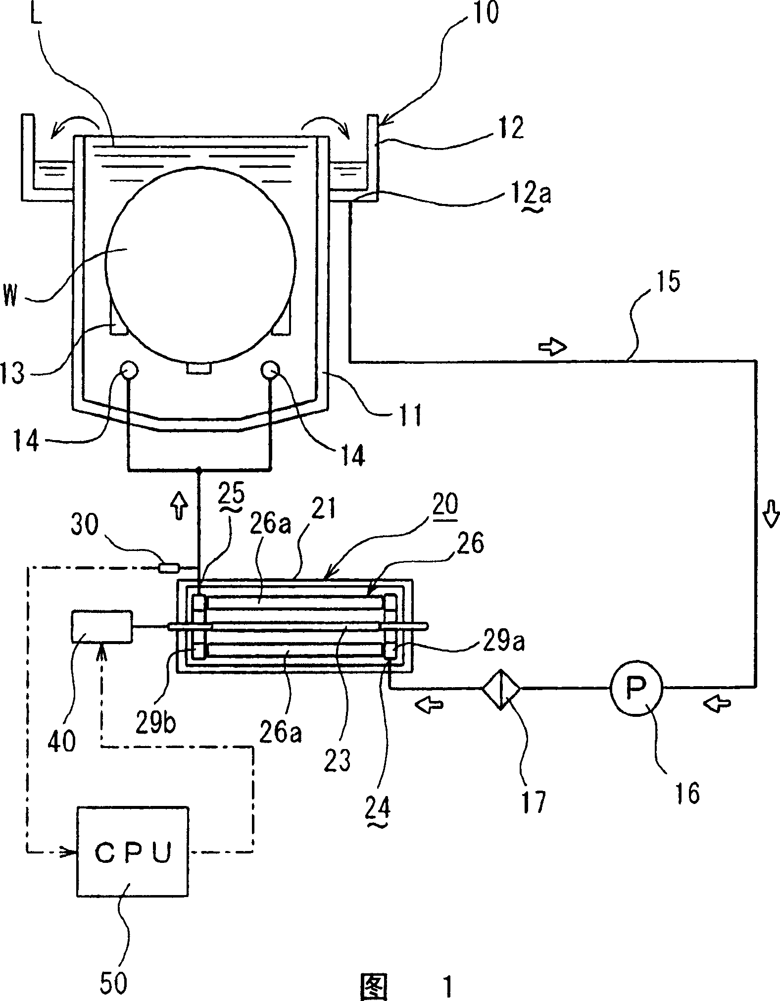
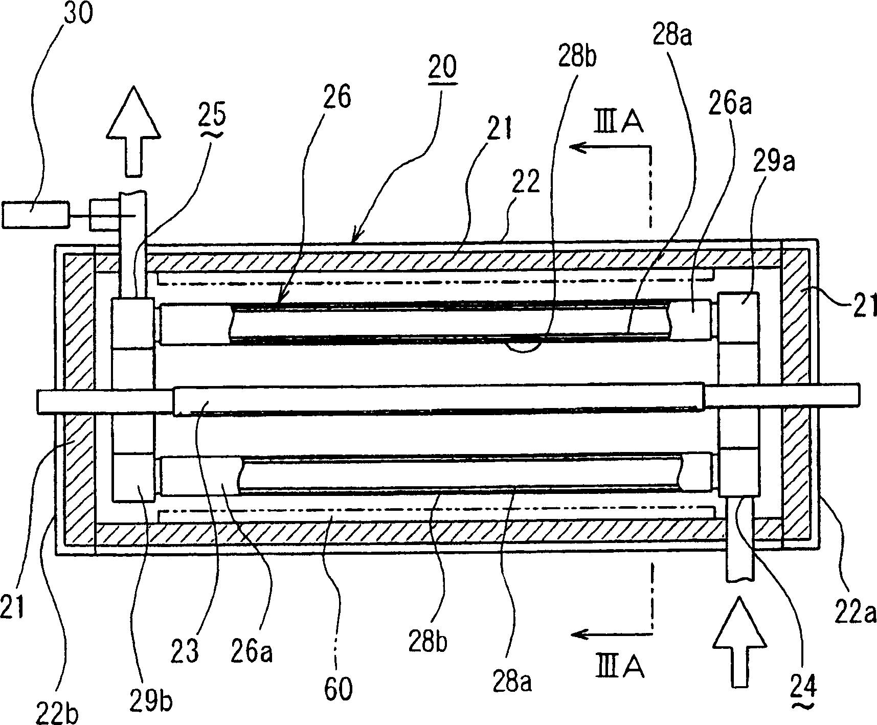
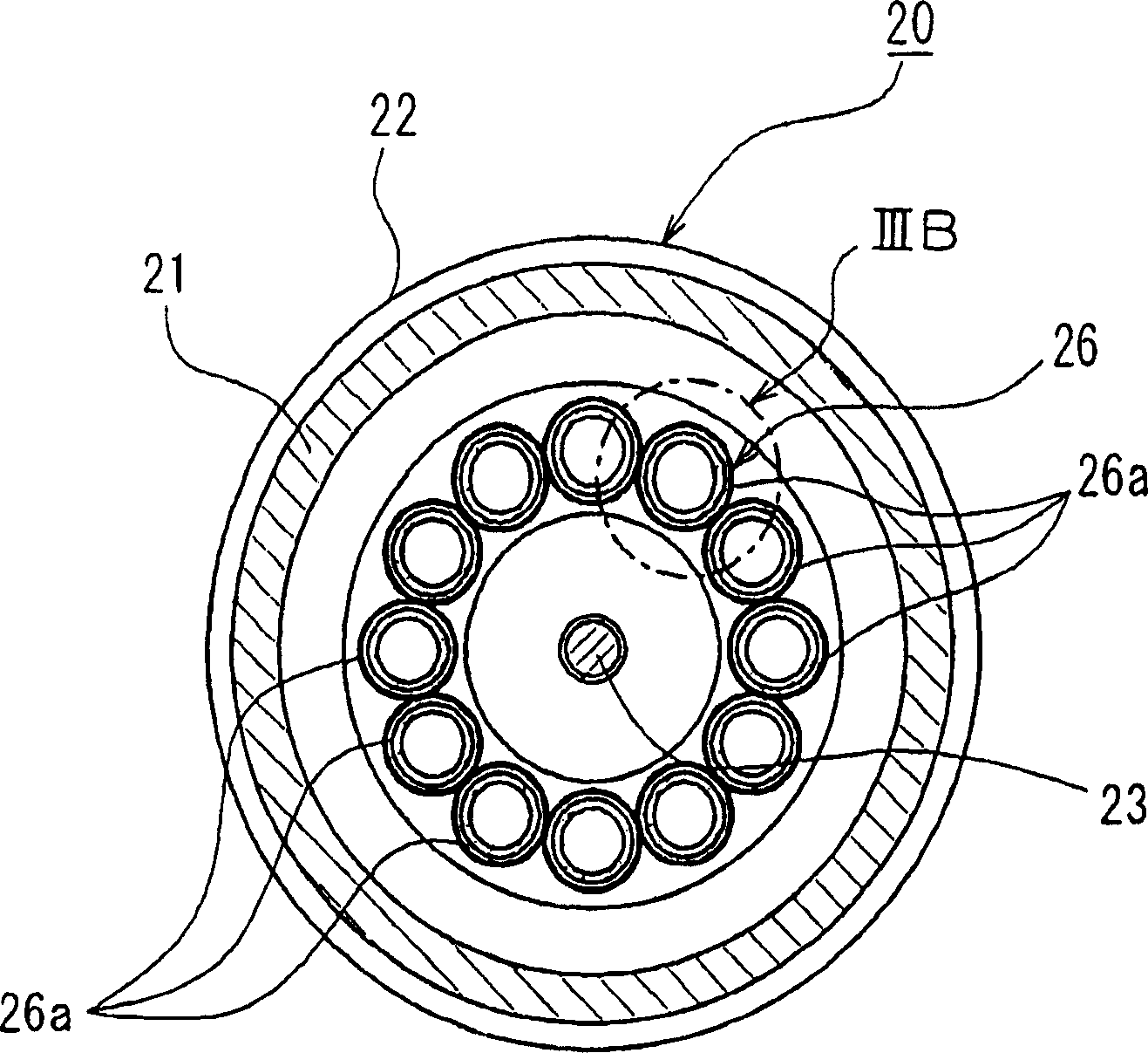
[0030] A fluid heating device and a cleaning system equipped with a fluid heating device in a first embodiment of the present invention will be described with reference to FIGS. 1 , 2 , 3A, and 3B.
[0031] Referring to Fig. 1, the cleaning system includes: a cleaning box 10 having an inner box 11 containing a cleaning liquid L such as dilute hydrofluoric acid (DHF) or flushing liquid (eg, deionized water) and an upper opening around the inner box 11 to receive The outer case 12 of the cleaning liquid overflowing from the inner case 11; the cleaning liquid supply nozzle 14 arranged in the lower area of the interior of the inner case 11; the circulation passage 15 having a first end connected to the cleaning liquid supply nozzle 14 and arranged in the outer case The second end of the discharge opening 12a at the bottom of 12. A circulation pump 16, a filter 17, and a fluid heating device 20 are sequentially arranged in the circulation passage 15 from the side of the discharge...
no. 2 example
[0041] will refer to Figure 4A , 4B , 5A and 5B describe a fluid heating device in a second embodiment of the present invention.
[0042] In the second embodiment of the fluid heating apparatus 20A, the tubular structure 26A comprises a single tube 70 wound in a helical configuration around the heat lamp 23 to form a tube shape. The tubular structure 26A surrounds the halogen lamp 23, while an annular gap is formed between the halogen lamp 23 and the tubular structure 26A. The helical axis of the tube 70 coincides with the longitudinal axis of the halogen lamp 23 . In consideration of heating efficiency, adjacent portions of the tube 70 with respect to the direction of the helical axis are preferably in close contact with each other, but may also be very close while maintaining a small gap therebetween as long as radiant light emitted from the halogen lamp 23 can be prevented or suppressed. (heat radiation) leakage to a negligible level is sufficient. Tube 70 has one end ...
no. 3 example
[0046] Figures 6A, 6B, 7A and 7B show the use of IPA steam and N 2 A mixed gas of gas dries an IPA drying system of a semiconductor wafer equipped with a fluid heating apparatus 20B in a third embodiment of the present invention. The IPA drying system includes: a processing container 80 adapted to house a semiconductor wafer W (i.e., a processing object) therein; a fluid supply nozzle 81 for spraying IPA vapor and N toward the semiconductor wafer W housed in the processing container 80. 2 Mixed gas of gas; fluid heating device 20B in the third embodiment according to the present invention; and for using N 2 Two-fluid nozzle 82 for gas atomized IPA liquid.
[0047] The fluid heating device 20B in the third embodiment differs from the fluid heating device 20A in the second embodiment only in the following points.
[0048] First, the cross-sectional structure of the coiled tube 70A of the fluid heating device 20B is different from the cross-sectional structure of the coiled tub...
PUM
 Abstract
Description
Claims
Application Information