Plate type heat exchanger and method of manufacturing the same

A manufacturing method and flat-plate technology, applied in indirect heat exchangers, cooling/ventilation/heating transformation, heat exchange equipment, etc., can solve the problem of reduced cooling capacity of heat pipes, unsmooth phase change and movement of working fluid, and sealing operations In order to achieve the effect of high cooling efficiency, suppress the deviation of heat carrier transfer ability, and prevent the working fluid from boiling

Inactive Publication Date: 2007-01-10
NAKAMURA IND MFG CO LTD
View PDF2 Cites 29 Cited by
  • Summary
  • Abstract
  • Description
  • Claims
  • Application Information

AI Technical Summary

Problems solved by technology

In such a vacuum state, the working fluid sometimes boils, and there is a problem that it is difficult to inject the working fluid
In addition, when the mating surfaces of the body member and the cover member are sealed so that the hollow part forms an airtight structure, there is also the problem that the sealing operation is extremely difficult due to the vacuum state in the vacuum furnace.
[0015] Therefore, insufficient working fluid is caused, the amount of working fluid in the evaporator is insufficient, and the heat-generating parts cannot be cooled sufficiently, so that the temperature o

Method used


Image

  • Plate type heat exchanger and method of manufacturing the same
  • Plate type heat exchanger and method of manufacturing the same
  • Plate type heat exchanger and method of manufacturing the same

Examples


Embodiment 1

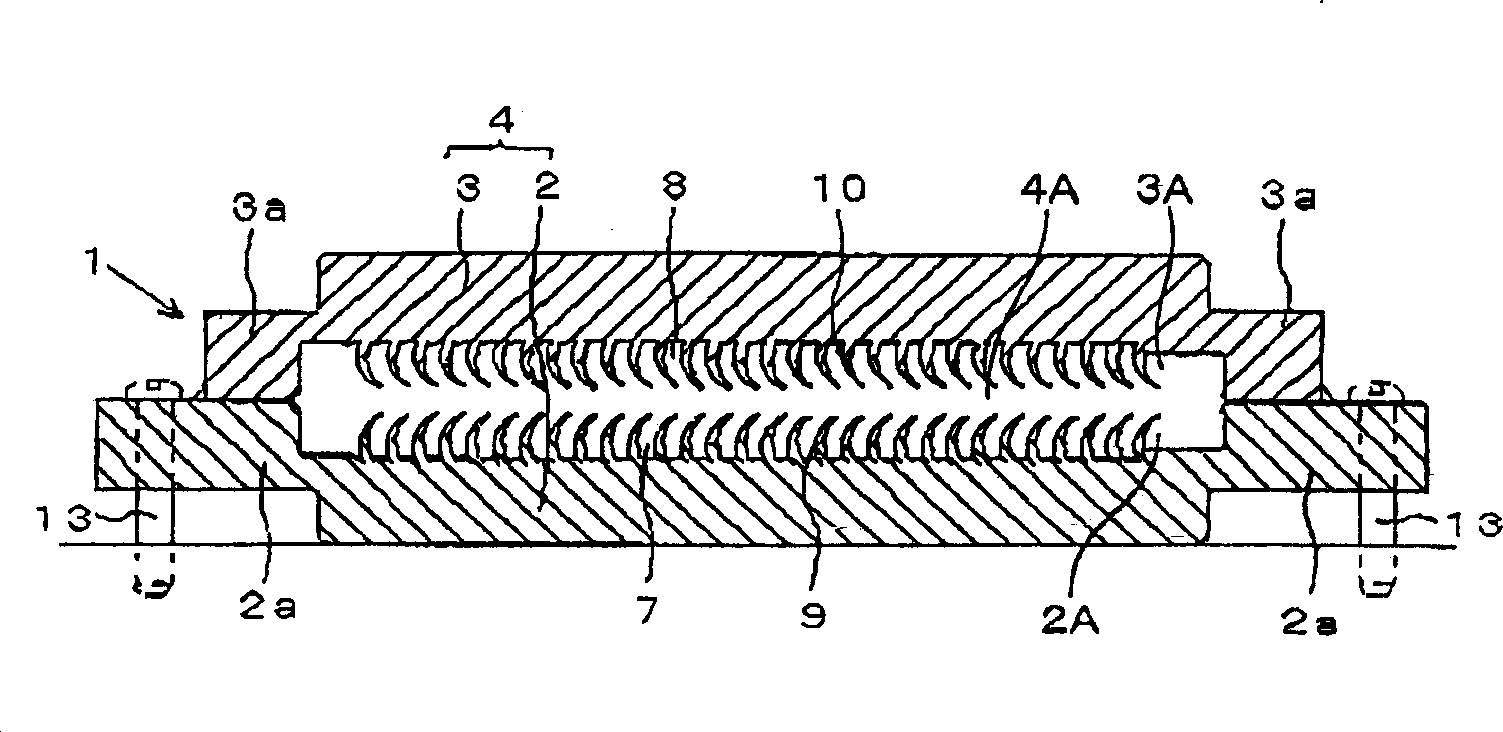
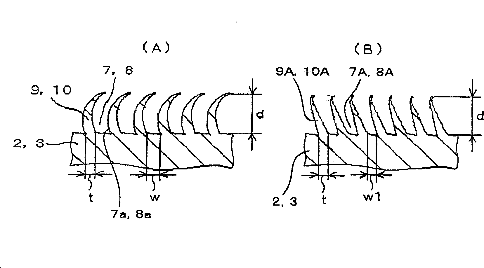
[0084] figure 1 It is a sectional view showing the flat heat pipe of Example 1, figure 2 is a plan view showing a flat heat pipe. The flat heat pipe 1 is sealed with a working fluid (heat carrier) in a hollow portion 4A of an airtight structure formed inside a flat rectangular container 4, and a guide groove as a heat carrier is formed on the inner surface portion of the container facing the hollow portion 4A. A plurality of grooves 7,8. The grooves 7 and 8 are formed between the condensation part 6 and the evaporation part 5 in the hollow part 4A, and the working fluid moves along the grooves 7 and 8 from the condensation part 6 to the evaporation part 5 by capillary force to dissipate heat.

[0085] The flat container 4 includes a rectangular lower container (container body) 2 and a rectangular upper container (container cover) 3 that covers the lower container 2, and the flat container 4 is formed by connecting the two rectangular frames Shaped mating surfaces, that is,...

Embodiment 2

[0134] Figure 17 is a cross-sectional view showing a flat heat pipe as a liquid-cooled flat heat exchanger according to Embodiment 2 of the present invention, Figure 18 is a plan view showing a flat heat pipe, Figure 19 It is a perspective view partially cut away of a flat heat pipe.

[0135] The container 104 of the flat heat pipe 101 includes a lower container 102 and a sealing member 103 covering the lower container 102 , and the container 104 is formed by joining and sealing the peripheries of both. A flat hollow portion 104A of an airtight structure is formed inside the container 104 . The sealing member 103 is formed in a substantially dish shape having a concave portion, and a groove portion 107 connecting the evaporating portion 105 and the condensing portion 106 is formed on the inner surface of the substantially flat plate-shaped lower container 102 . And, a working fluid is sealed in such a sealed hollow portion 104A. As the working fluid, pure water, substit...


PUM

PropertyMeasurementUnit
Plate thicknessaaaaaaaaaa
Bottom widthaaaaaaaaaa
Depthaaaaaaaaaa

Abstract

A method for manufacturing a plate-type heat exchanger in which a heat medium is sealed in a hollow part of an airtight structure formed in the interior of a plate-like container, and the heat medium is moved by capillary force from a condensing part to an evaporating part in the hollow part along heat-medium-guiding grooves formed in the container's inside surface portions that face the hollow part; wherein a plastic workable metal plate of specific thermal conductivity is prepared; a carving tool is used to repeatedly carve out a surface portion of the metal plate at specific intervals along the surface portion, forming a plurality of plate-like fins; and a plurality of grooves formed between these fins is used as heat-medium-guiding grooves. A plate-type heat exchanger is obtained which comprises extremely small heat-medium-guiding grooves that have the necessary capillary force to move the heat medium from the condensing part to the evaporating part without affecting the set alignment or other such characteristics.

Description

technical field [0001] The present invention relates to a flat heat exchanger suitable for use as a flat heat pipe, a vapor chamber, etc. for cooling heat generating bodies such as semiconductor chips and integrated circuit boards, and a method for manufacturing the same. Background technique [0002] In recent years, computer equipment tends to be more and more miniaturized and high-performance. As the performance increases, the heat generated by semiconductor elements and integrated circuits also increases. If an effective cooling method for these components can be provided, further miniaturization and high performance of computer equipment can be promoted. [0003] In order to cool high-output, highly-integrated chips and the like, various cooling systems have been proposed. As such a cooling system, a liquid-cooled heat exchanger typified by a heat pipe has attracted attention. Heat pipes that are liquid-cooled heat exchangers are classified into circular tube-shaped h...

Claims


Application Information

Patent Timeline
IPC IPC(8): F28D15/02H05K7/20
CPCF28F3/048F28D15/046F28D15/0233B21J5/068H01L2924/0002H01L2924/00
Inventor 宫原英行
Owner NAKAMURA IND MFG CO LTD
Why Eureka
Try Eureka