Thin loop type radiating apparatus

A technology of heat dissipation device and loop, which is applied to circuits, indirect heat exchangers, lighting and heating equipment, etc., can solve the problems of poor working liquid return and steam damage, etc.

Inactive Publication Date: 2007-01-10
FU ZHUN PRECISION IND SHENZHEN +1
View PDF0 Cites 17 Cited by
  • Summary
  • Abstract
  • Description
  • Claims
  • Application Information

AI Technical Summary

Problems solved by technology

[0005] In order to solve the technical problems of unsmooth return flow of the working liquid in the loop heat pipe and the destruction of heat transfer in one direction by steam, it is necessary to provide a thin loop heat sink that can circulate in one direction and transfer heat efficiently

Method used


Image

  • Thin loop type radiating apparatus
  • Thin loop type radiating apparatus
  • Thin loop type radiating apparatus

Examples


Embodiment Construction

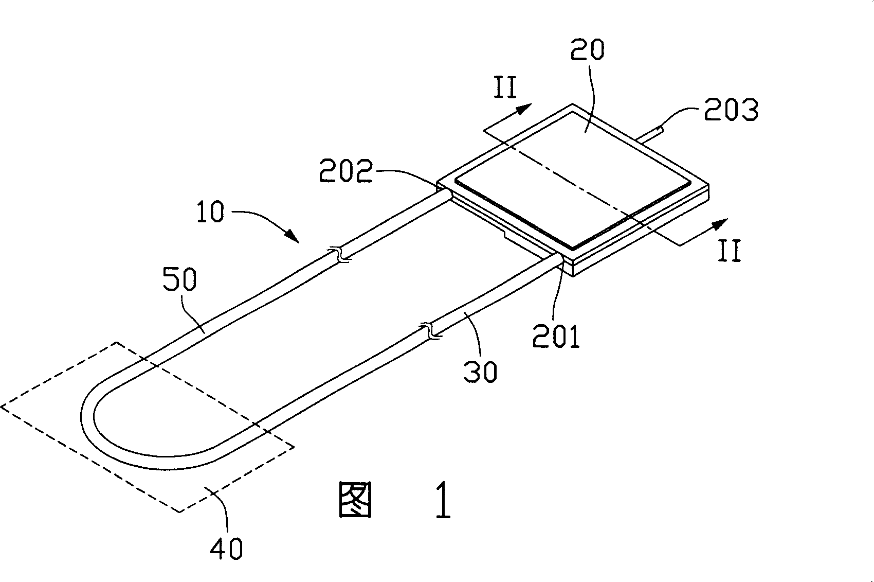
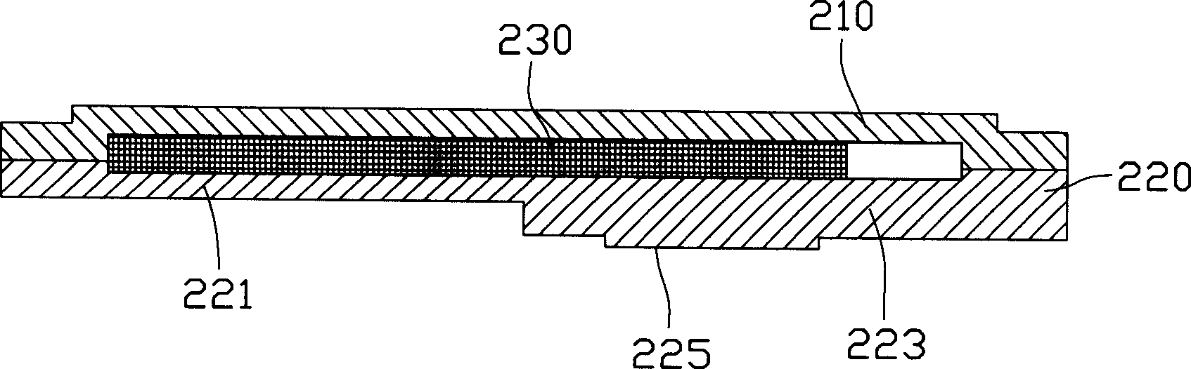
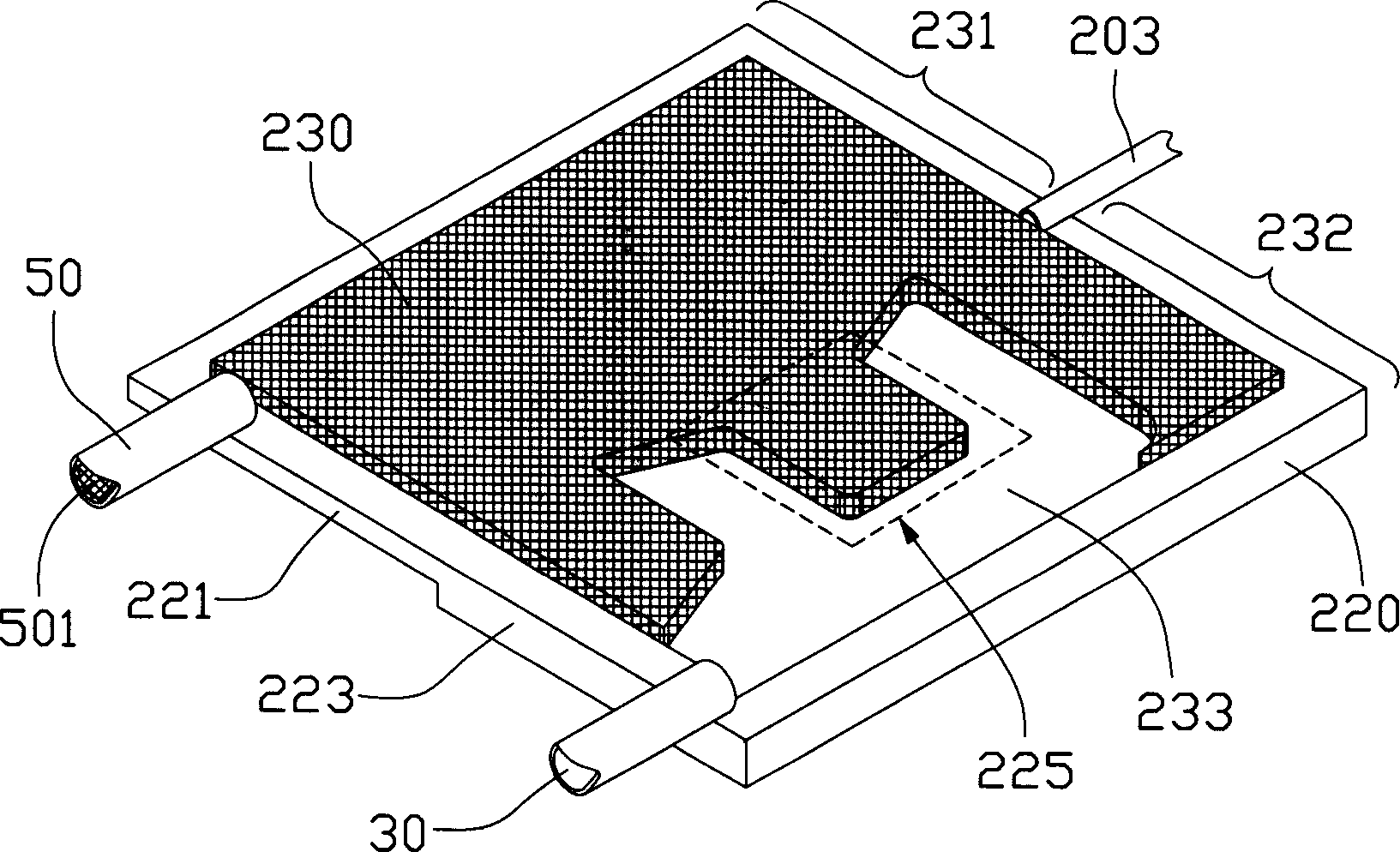
[0020] FIG. 1 is a schematic perspective view of a first embodiment of a thin loop heat dissipation device of the present invention. The heat dissipation device 10 includes an evaporator 20 , a steam conduit 30 , a condenser 40 and a return conduit 50 . One side wall of the evaporator 20 is respectively provided with an outlet 201 and an inlet 202 at opposite positions, and the steam conduit 30 and the return conduit 50 are coilable metal or coilable non-metallic pipes, respectively communicating with the outlet of the evaporator 20 201 is connected to the inlet 202 and to the remote condenser 40, so as to communicate with each other to form a heat conduction tight loop. The condenser 40 can be any existing heat dissipation structure, such as heat dissipation fins, fans, water circulation heat dissipation devices, etc., aiming at releasing heat from the steam transferred here and cooling it into a liquid state. The evaporator 20 is formed in a flat plate shape, combined with ...


PUM


Abstract

The heat sink includes an evaporator, a condenser, a steam conduit, and a backflow conduit. A cavity is formed in the evaporator, and working fluid is filled to the cavity. The cavity is divided into evaporation section and channel section of micro flow in liquid phase. After absorbing quantity of heat in the evaporation section, the working fluid generates steam, which through the steam conduit reaches to the condenser, where steam is cooled to liquid state. Through the backflow conduit, the cooled liquid is returned back to the condenser so as to constitute an airtight heat exchange loop. Structure for reducing steam cumulated on channel section is setup on the evaporator in order to reduce resistance for working fluid to flow back to the evaporation section. Thus, the invention guarantees circulation in one direction, and high efficiency for transferring heat.

Description

【Technical field】 [0001] The invention relates to a heat dissipation device, in particular to a thin loop type heat dissipation device which can quickly dissipate the heat of a heating component without external power. 【Background technique】 [0002] With the rapid development of the electronic information industry, high-tech electronic products are moving towards thinner, smaller, multi-functional, and faster development trends. However, as the operating frequency and speed of electronic components continue to increase, the heat released per unit area will (Heat flux) is getting higher and higher, which seriously threatens the operation performance and stability of electronic components, and even burns these expensive electronic components due to high temperature. The quality of the cooling device will directly affect the life and operation quality of electronic components. In order to ensure the normal operation of the electronic components, it is necessary to dissipate he...

Claims


Application Information

Patent Timeline
Patent Type & Authority Applications(China)
IPC IPC(8): H01L23/427G06F1/20H05K7/20
CPCF28D15/043F28D15/0266H01L2924/0002H01L2924/00
Inventor 刘泰健童兆年侯春树范智峰杨志豪
Owner FU ZHUN PRECISION IND SHENZHEN
Why Eureka
Try Eureka