Piston for internal combustion engine

A technology for internal combustion engines and pistons, applied in the field of improving the cooling performance of pistons, to achieve low cost, simple structure, and the effect of suppressing temperature rise

Inactive Publication Date: 2007-01-24
KOMATSU LTD
View PDF1 Cites 10 Cited by
  • Summary
  • Abstract
  • Description
  • Claims
  • Application Information

AI Technical Summary

Problems solved by technology

that is image 3 The dot-dash line parts a and b shown will cause oil coking

Method used


Image

  • Piston for internal combustion engine
  • Piston for internal combustion engine
  • Piston for internal combustion engine

Examples


no. 1 example

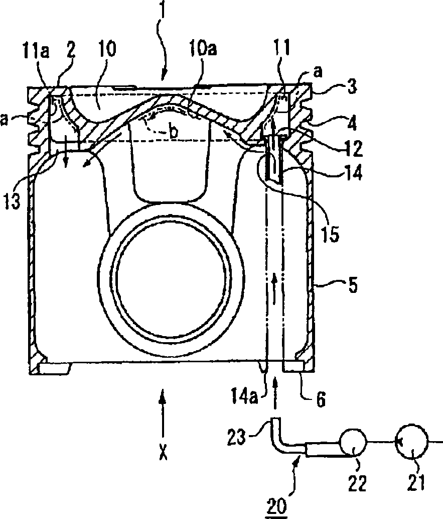
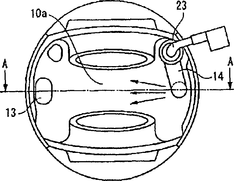
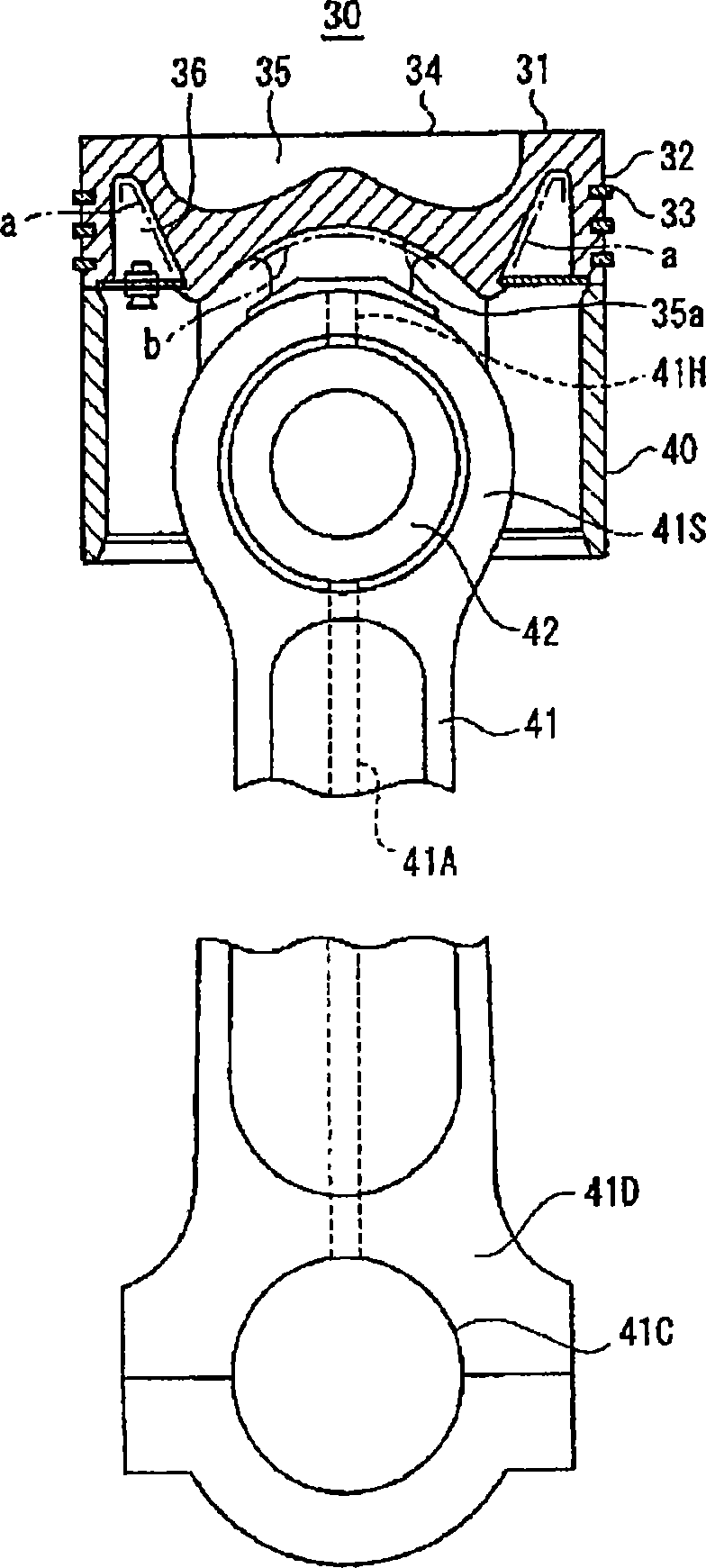
[0046] Figure 4 It is a side cross-sectional view showing the casting integral type piston head of the first embodiment of the present invention, Figure 5 It is a side cross-sectional view showing a hinged type piston head.

[0047] In this example, in Figure 4 Among them, the surface roughness of the back surface 10a of the combustion chamber 10 of the piston 1 and the inner wall 11a of the cooling cavity 11 is 6.3S. In addition, in Figure 5 Among them, the surface roughness of the back surface 35a of the combustion chamber 35 of the articulated piston 30 and the inner wall 36a of the cooling groove 36 is less than or equal to 6.3S. Specifically, in Figure 4 , Figure 5 The surface roughness of at least the two-dashed line parts a' and b' shown above is less than or equal to 6.3S. Double dotted line part a', b' part and figure 1 , image 3 The two-dot dash line part a, b part corresponds to.

[0048] However, it is also conceivable to make only the surface rough...

no. 2 example

[0052] In the second embodiment of the present invention, same as the first embodiment, on the piston 1, the surface roughness of the back surface 10a of the combustion chamber 10 and / or the inner wall 11a of the cooling cavity 11 is less than or equal to 6.3S, in On the piston 30, the surface roughness of the back surface 35a of the combustion chamber 35 and / or the inner wall 36a of the cooling groove 36 is less than or equal to 6.3S, and further, the surface roughness of the surface is less than or equal to 6.3S. coating.

[0053] The surface coating of this example is Figure 6 The self-purifying catalyst film 50 is shown.

[0054] The self-purifying catalyst film 50 is composed of a catalyst, a heat-resistant bonding material (glass frit), and a porous texture (matte) forming material, which has the function of oxidizing and burning the attached oil into water vapor and carbon dioxide in a non-flame state by catalytic action. function. In addition, when the engine is op...

no. 3 example

[0061] In the third embodiment of the present invention, as Figure 7 As shown, as the surface coating, instead of the self-purifying catalyst film 50 of the second embodiment, a catalyst-free enamel coating film 60 is used. The film 60 is formed from a single layer of catalyst-free enamel parts. The composition of the enamel may be the same as that of the heat-resistant bonding material of the second embodiment, and a composition generally used for low-temperature enamel-type enamel coating may be applied. The thickness of the film 60 should be determined in consideration of the influence on the cooling effect, which is about 2-1000 μm.


PUM


Abstract

A piston (1), wherein the surface roughnesses of the rear surface (10a) of a combustion chamber (10) and the inner wall surface (11a) of a cooling cavity (11) are set to 6.3 S or less (portions a' and b' indicated by chain-double dashed lines), and these portions with the surface roughness of 6.3 S or less are surface-coated with the film of a self-purifying catalyst. Since oil is less accumulated in the surface-coated portions, the caulking of the oil can be suppressed to prevent the coefficient of heat transfer from being deteriorated so as to suppress the rise of temperature, and accordingly, the strength of the piston can be prevented from being lowered by the caulking. As a result, since an increase in the amount of a cooling oil and an increase in the capacity of an oil cooler due to an increase in the output of an engine can be eliminated, the piston (1, 30) for the internal combustion engine simple in structure and capable of easily coping with an increase in the output of the engine can be provided without causing an increase in installation space and cost.

Description

technical field [0001] The present invention relates to a piston for an internal combustion engine, and more particularly to a means for improving the cooling performance of a piston used in a high-speed, high-output diesel engine having a piston cooling device using engine oil. Background technique [0002] Conventionally, as a piston cooling device in a high-output diesel engine, there is a piston cooling device for an internal combustion engine described in Patent Document 1, for example. [0003] figure 1 It is a side sectional view showing the structure of a piston for an internal combustion engine and a piston cooling device described in Patent Document 1, figure 2 yes figure 1 X-direction view. and, figure 1 yes figure 2 The A-A direction view. [0004] exist figure 1 , figure 2 Among them, the piston 1 as the first conventional example is a casting (for example, FCD: spheroidal graphite cast iron). A concave combustion chamber 10 opening upward is provide...

Claims


Application Information

Patent Timeline
Patent Type & Authority Applications(China)
IPC IPC(8): F02F3/22F02F3/10F16J1/09F02F3/12F02F3/14F16J1/01F16J1/08
CPCF05C2253/12F02F3/12F02F3/22F02F3/14F16J1/01F16J1/08F02F3/10F16J1/09
Inventor 三原健治
Owner KOMATSU LTD
Why Eureka
Try Eureka