Shape memory alloy wire driven pectoral wave pushing bionic underwater robot
A memory alloy wire and underwater robot technology, applied in the field of robots, can solve the problems of small output force, complex structure, high noise, etc., and achieve the effects of small quality, high swimming efficiency, and simple sealing
- Summary
- Abstract
- Description
- Claims
- Application Information
AI Technical Summary
Problems solved by technology
Method used
Image
Examples
specific Embodiment approach 1
[0019]Shape memory alloy belongs to a kind of intelligent material, which is a new type of functional material with shape memory effect, which can sense temperature and displacement, and convert thermal energy into mechanical energy. Since the discovery of the shape memory effect (SME, Shape Memory Effect) in the nearly equiatomic ratio TiNi alloy in the early 1960s, dozens of shape memory alloys have been discovered so far, among which TiNi and Cu-Zn-Al alloys have been Entering the industrial stage, Cu-Al-Ni and Fe-Mn-Si alloys have entered the market introduction stage. The shape memory effect means that some alloys that exhibit martensitic transformation are deformed when they are in a low-temperature phase, and when heated to a critical temperature (reverse transformation point), martensite (Martensite) transforms into austenite (Austenite) through reverse transformation. , the phenomenon of returning to its original shape. The shape memory effect can be divided into one...
specific Embodiment approach 2
[0030] Embodiment 2: The difference between this embodiment and Embodiment 1 is that, referring to FIG. 30 , an external joint 10 is connected to the other end of the pectoral fin undulation joint 3 connected to the body 1 , and the structure of the external joint 10 is consistent with the pectoral fin undulation The joints 3 are the same, the distal end of each pectoral fin undulating joint 3 can only be connected to one external joint 10, and can also be connected to multiple external joints in sequence, so as to realize the needs of high-speed movement, between the pectoral fin undulating joint 3 and the external joint 10 and along the The multiple external joints of the secondary connection are all connected through the base body 9 . The shape memory alloy wires 6 on the pectoral fin undulation joint 3 and the shape memory alloy wires on each external joint 10 are respectively connected to their respective wires to realize separate control, so that different bending amplitu...
specific Embodiment approach 3
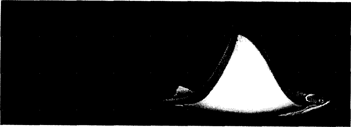
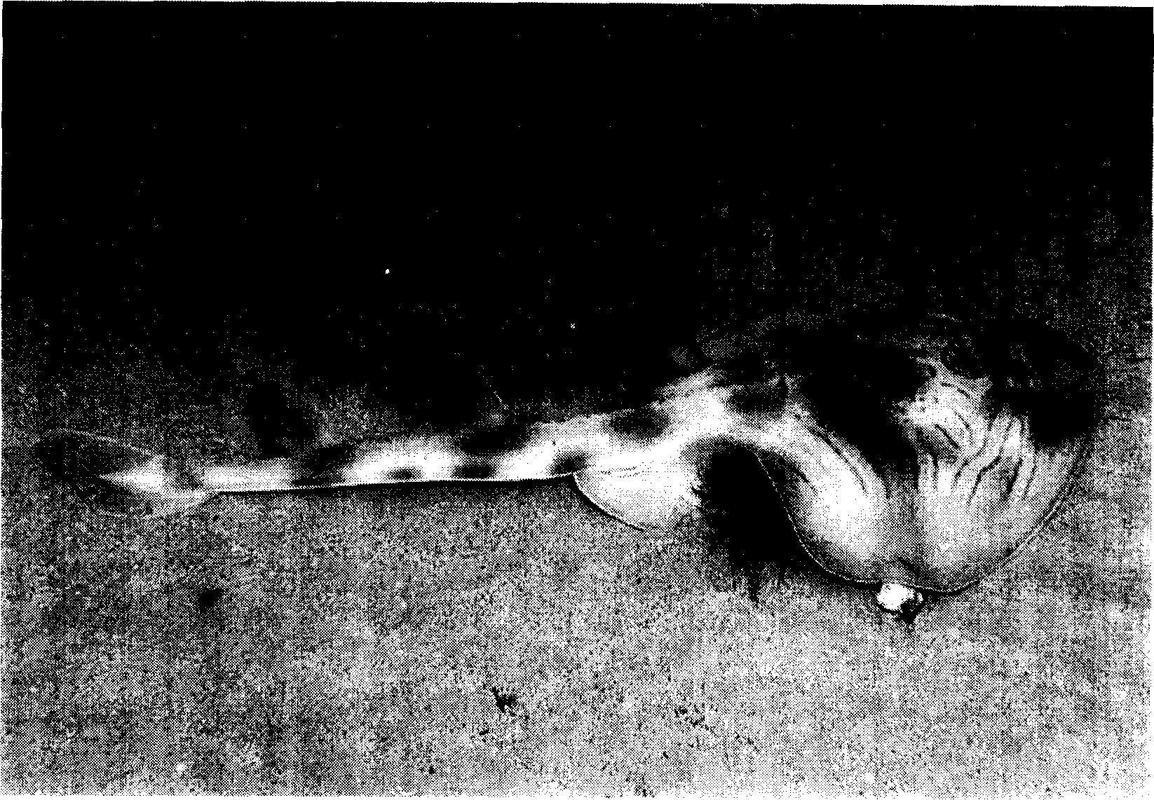
[0038] Specific Embodiment Three: This embodiment is a bionic underwater robot propelled by four single-segment pectoral fin fluctuations. The so-called single-segment pectoral fin fluctuation joint means that the other end of the pectoral fin fluctuation joint of the robot is no longer connected to an external joint. Its outline Such as Figure 11As shown in the figure, four single-segment pectoral fin undulating joints and one rudder flexible joint are used, which imitate the action of the eastern crab ray to achieve motion. Figure 32 , Figure 33 An exploded view of the structure for the thruster arrangement of the biomimetic robot, where Figure 32 is a schematic diagram of the parallel connection method between shape memory alloy wires, Figure 33 It is a schematic diagram of the series connection method between shape memory alloy wires. The underwater robot adopts the cable-free control method, and the sequence of its pectoral fin joint movement is as follows: Figu...
PUM
 Abstract
Description
Claims
Application Information
 - R&D
- Intellectual Property
- Life Sciences
- Materials
- Tech Scout
- Unparalleled Data Quality
- Higher Quality Content
- 60% Fewer Hallucinations
Browse by: Latest US Patents, China's latest patents, Technical Efficacy Thesaurus, Application Domain, Technology Topic, Popular Technical Reports.
© 2025 PatSnap. All rights reserved.Legal|Privacy policy|Modern Slavery Act Transparency Statement|Sitemap|About US| Contact US: help@patsnap.com


