Plasma collision offect propeller

A technology of plasma and impact effect, which is applied in the direction of using plasma, propulsion system devices of space vehicles, thrust reversers, etc., and can solve the problems of slowness and limited thrust.

Inactive Publication Date: 2007-01-31
李晓辉 +1
View PDF0 Cites 12 Cited by
  • Summary
  • Abstract
  • Description
  • Claims
  • Application Information

AI Technical Summary

Problems solved by technology

Electric rocket motors have high specific impulse, but they produce limited thrust and can only propel small objects at relatively slow speeds in a vacuum

Method used


Image

  • Plasma collision offect propeller
  • Plasma collision offect propeller
  • Plasma collision offect propeller

Examples


Embodiment Construction

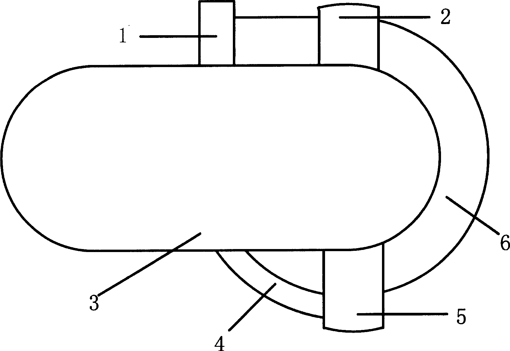
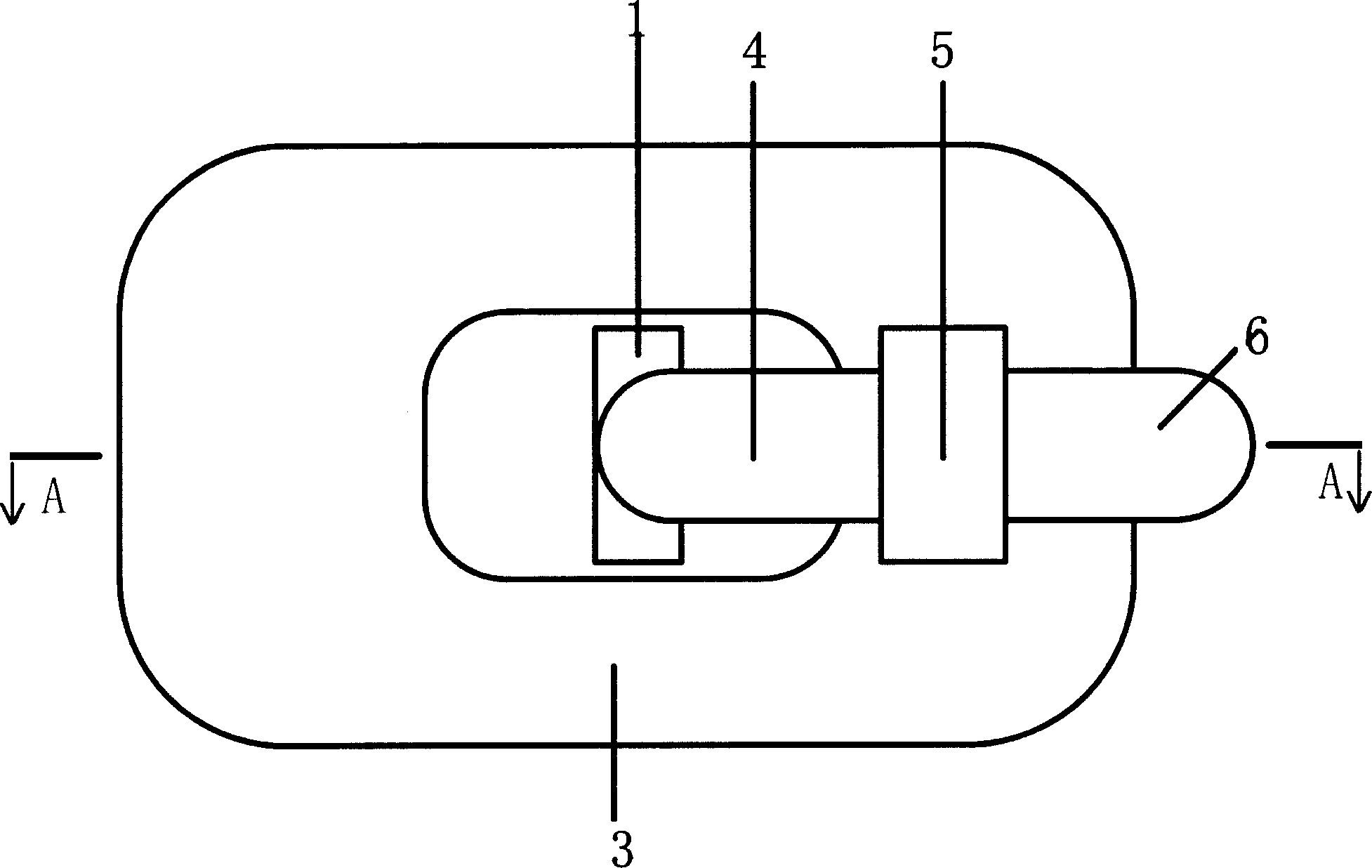
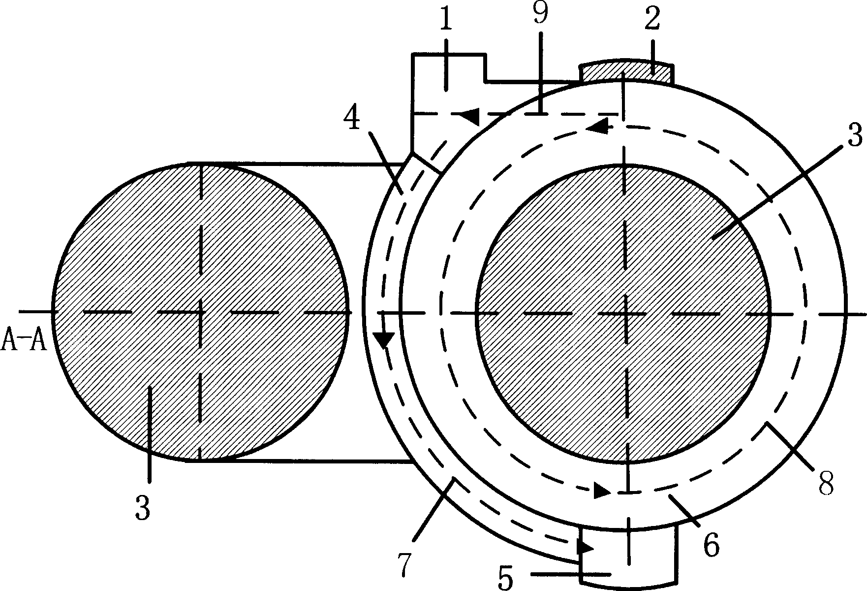
[0079] As a complete propulsion system, the plasma impact thruster usually includes an ion impact and recovery device, an off-track magnetic field generator, a U-shaped electromagnet, a gas circulation channel, a gas ionization device, an induced electric field accelerator and a control device.

[0080] The working process of the thruster can be clearly seen from the accompanying drawings: the gas enters the acceleration orbit of the induced electric field accelerator (6) after being ionized, and after the gas positive ions reach a certain speed, the off-track magnetic field generator (2) is used to The generated magnetic field perpendicular to the plane of the gas ion acceleration track (8) changes the trajectory of the ion, making it move towards the negatively charged target plate, and the high-speed moving ion hits the target plate, so that the thruster produces the same direction as the ion movement direction. Momentum in the direction of the ions, while the ions capture e...


PUM


Abstract

A plasma knock-on effect thruster is a propulsion motor without consuming propelling medium. Because of not requiring the consumption of too much fuel, the thruster can make the spacecraft have more spaces to load the payload suitable for the attitude control of the spacecraft or a long-distance, long-time space navigation. The principle of the invention is that: by the action of the induced electric field the plasma is made to accelerate and knock on the member fixed with the spacecraft together, so as to change the momentum of the spacecraft. The plasma as the propelling medium can be used cyclical and the needed energy is only the electric energy.

Description

Technical field: [0001] The present invention is a propulsion engine that does not need to consume propellant medium, its propellant medium—plasma can be recycled, and the required energy is only electric energy. Because it does not need to consume a large amount of fuel, it can enable the space vehicle to have more space to load payloads, and is suitable for attitude control of space vehicles or long-distance and long-time space travel. Background technique: [0002] The space engine most familiar to human beings should be the rocket engine, but the shortcomings of this engine are obvious. The volume and weight occupied by chemical fuel are too large, the thrust is too small, and the efficiency is limited. Therefore, scientists from various countries have come up with various more advanced engines: nuclear engines, interstellar ramjet engines, antimatter engines, ion engines, photon engines, and even thought of using the light pressure and stellar wind of stars to raise lig...

Claims


Application Information

Patent Timeline
Patent Type & Authority Applications(China)
IPC IPC(8): F03H1/00H01H1/00B64G1/40
CPCF03H99/00
Inventor 李晓辉
Owner 李晓辉
Why Eureka
Try Eureka