Heat exchanger, method for manufacturing the same, and heat exchanging tube
A technology of heat exchanger and thermal spraying, which is applied in the field of heat exchanger tubes, can solve problems such as difficult to use manufacturing methods, and achieve the effect of improving corrosion resistance and preventing fins from detaching
- Summary
- Abstract
- Description
- Claims
- Application Information
AI Technical Summary
Problems solved by technology
Method used
Image

Examples
example 1
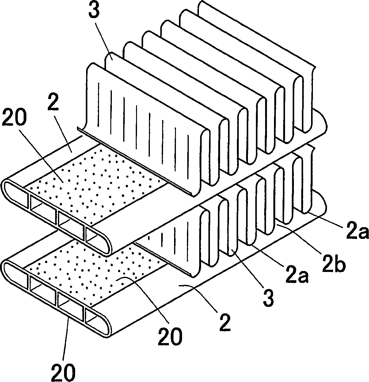
[0087] Using an extruded material made of aluminum alloy (0.4wt% copper-0.15wt% manganese-the rest is aluminium), an extruder with a width of 16mm, a height of 3mm and a wall thickness of 0.5mm can be extruded Flat perforated tube. On the other hand, above and below the exit of the extruder, thermal spray guns of an arc sprayer are installed to thermally spray zinc onto the upper and lower surfaces of the extruded tube to form a zinc thermal spray coating.
[0088] At this time, as shown in Table 1, the zinc adhesion amount in the zinc thermal spraying treatment was adjusted to 6g / cm 2 , and the area ratio to the entire tube surface was adjusted to 60%. Subsequently, the zinc thermal sprayed pipe 2 was subjected to zinc diffusion treatment of the zinc thermal sprayed layer in a nitrogen atmosphere furnace under heating conditions of 480° C.×2 hours. Thus, the zinc diffusion layer 20 is formed.
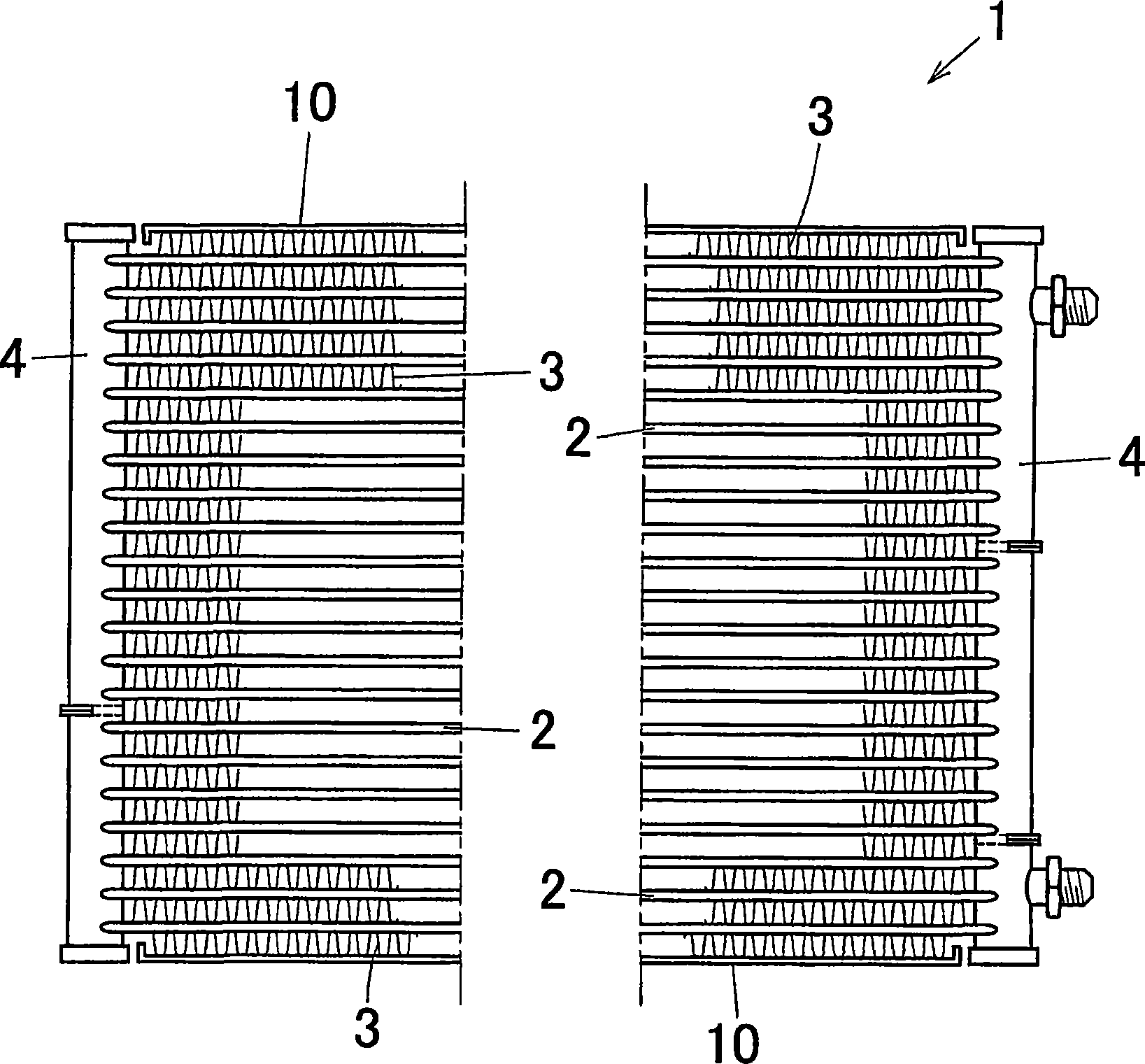
[0089] Use these tubes 20 to temporarily assemble into the multi-flow heat exch...
example 2
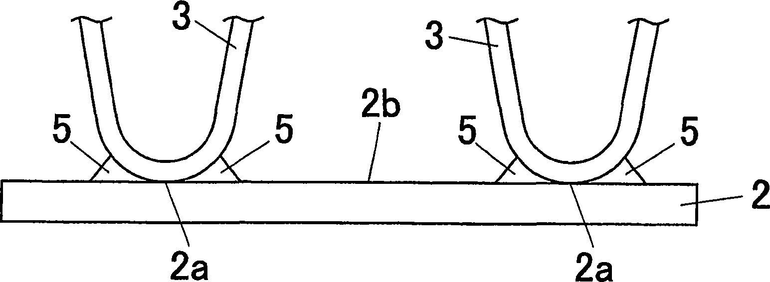
[0111] As shown in Table 1, the adhesion achieved by zinc thermal spraying treatment is set to 7g / cm 2 , and the area ratio is set to 65%. Diffusion treatment and brazing treatment were performed in the same manner as described above, and the zinc concentration of the surface between the fins and the maximum zinc concentration of the fillet eutectic portion were measured, and the same test was performed.
example 3
[0113] As shown in Table 1, the adhesion achieved by zinc thermal spraying treatment is set to 8g / cm 2 , and the area ratio is set to 70%. Diffusion treatment and brazing treatment were performed in the same manner as described above, and the zinc concentration of the surface between the fins and the maximum zinc concentration of the fillet eutectic portion were measured, and the same test was performed.
PUM
| Property | Measurement | Unit |
|---|---|---|
| Adhesion | aaaaa | aaaaa |
| Depth | aaaaa | aaaaa |
| Depth | aaaaa | aaaaa |
Abstract
Description
Claims
Application Information
PatSnap Eureka turns technology decisions into work you can execute. Powered by our Innovation Knowledge Graph, it runs expert workflows across engineering, life sciences, materials and intellectual property. Get your review-ready output in minutes.


