
Process for producing synthetic resin film having molecular orientation controlled in md direction

A technology of synthetic resin and manufacturing method, which is applied in the fields of printed circuit manufacturing, flat products, and other household appliances, etc., and can solve problems such as film wrinkling, wrinkling, and difficulty in stably maintaining the balance of MD/TD characteristics

Active Publication Date: 2007-02-21
KANEKA CORP
View PDF0 Cites 0 Cited by
  • Summary
  • Abstract
  • Description
  • Claims
  • Application Information

AI Technical Summary

Problems solved by technology

However, in the manufacturing method described in this patent document, the end of the self-supporting polyamic acid film is fixed, heat-treated, stretched in the MD direction and the TD direction, and then the self-supporting polyamic acid film is slowly stretched. The method of slowly heating to imidize is different from the method of the present invention, and the stretching of the self-supporting polyamic acid film may have non-uniform properties of the stretched film
In addition, the specifically disclosed method is also a manufacturing method using batch processing, and there is no disclosure of a film that controls molecular orientation of the entire film in industrial continuous production.
[0007] Patent Document 2 proposes a method of stretching a fired polyimide film while annealing in the MD direction. When the imide film is stretched, it is often difficult to maintain a stable balance of properties in the MD / TD direction
In addition, in the case of a fired film, even if it can be stretched, the stretched film tends to be in the shape of a galvanized iron plate and has wrinkles, which is a practical problem.
[0008] Patent Document 3 proposes to apply 10kg / mm 2 The method for manufacturing a polyimide film with orientation control along the MD direction with the above tension zone stretching, the film tension produced by this proposal is too high, and the film after zone stretching produces wrinkles similar to galvanized iron plates along the TD direction. Practically unusable as a basement membrane

Method used

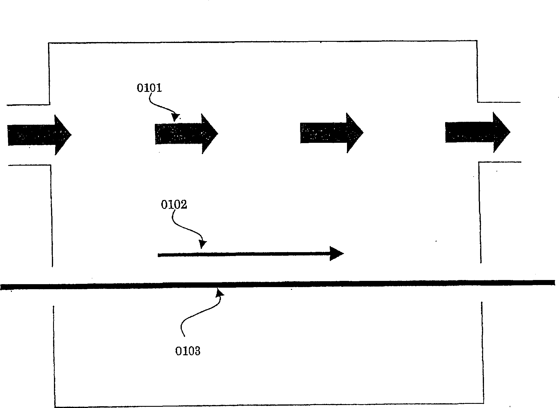
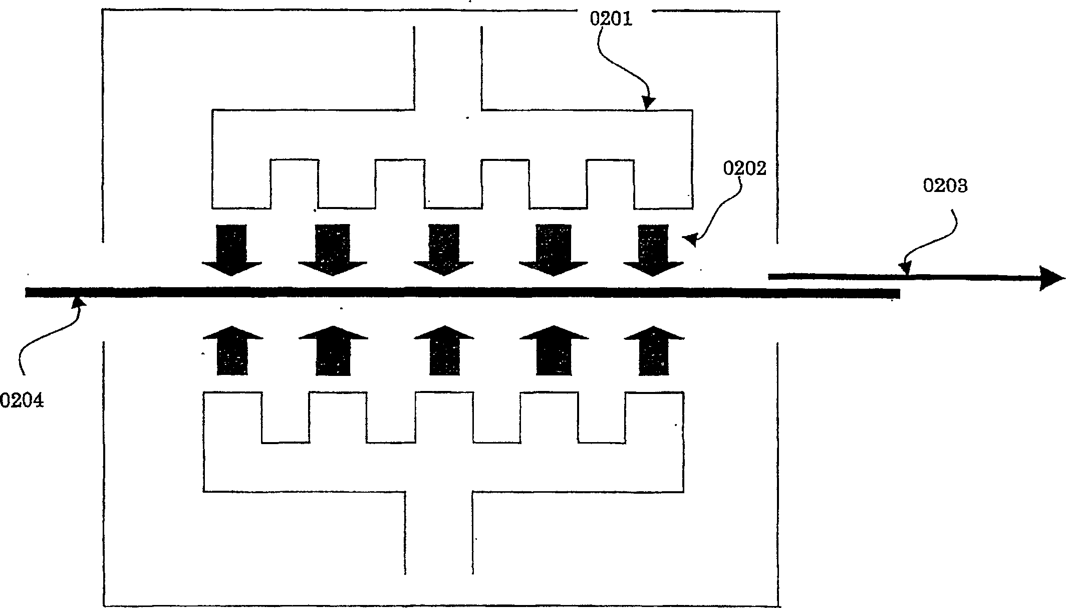
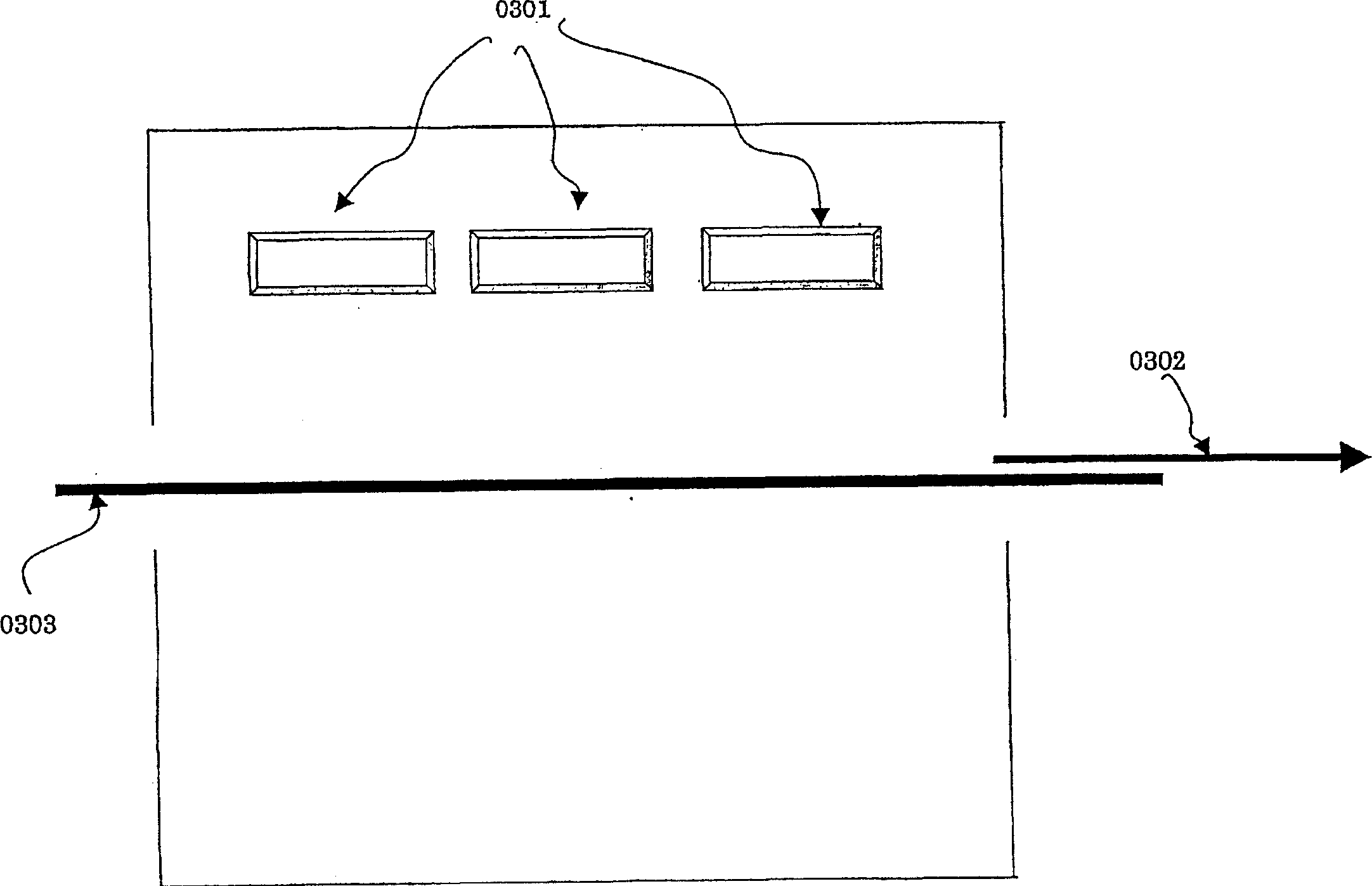

Image

  • Process for producing synthetic resin film having molecular orientation controlled in md direction
  • Process for producing synthetic resin film having molecular orientation controlled in md direction
  • Process for producing synthetic resin film having molecular orientation controlled in md direction

Examples


Embodiment

[0104] Hereafter, although an Example demonstrates this invention concretely, this invention is not limited only to an Example. In addition, evaluation of the molecular orientation angles of the thin films in Examples and Comparative Examples was performed as described below. In addition, Table 1 summarizes the production conditions of the thin films of Examples and Comparative Examples.

[0105] (Molecular orientation angle of film)

[0106] A sample of 4 cm x 4 cm was cut out and measured using a microwave molecular orientation meter MOA2012A manufactured by Oji Instruments.

[0107] Here, the molecular orientation angle θ is defined as follows.

[0108] Using the MOA2012 model, the orientation direction of molecules in the film plane (the maximum orientation of ε', where ε' is the dielectric constant of the sample) can be known as an angle value. In the present invention, a straight line indicating the orientation direction is taken as the "orientation axis" of the sampl...

manufacture example 1

[0114] Polymerize pyromellitic dianhydride / 4,4'-diphenylamine oxide / p-phenylenediamine in a molar ratio of 1 / 0.75 / 0.25 in N,N'-dimethylacetamide solvent, Make the solids fraction 18%. Specifically, 4,4'-diphenylamine oxide, which is 75 mol% relative to the total diamine components, is dissolved in N,N'-dimethylacetamide solvent, and then the full amount of pyromellitic dianhydride (ie relative An acid-terminated prepolymer was prepared from the charged diamine component of 133% acid anhydride). Then add the rest of the diamine component (ie, p-phenylenediamine) to the acid-terminated prepolymer solution, and add the insufficient amount of diamine so that it reacts substantially equimolarly with the total acid component to obtain a polymerization solution.

[0115]After cooling the polymerization solution to about 0°C, 2.0 moles of acetic anhydride and 0.5 moles of isoquinoline were added to 1 mole of amic acid in the polyamic acid organic solvent solution cooled to about 0°C,...

manufacture example 2

[0117] Put pyromellitic dianhydride / terephthalic acid anhydride / 4,4'-diaminodiphenyl ether / p-phenylenediamine in molar ratio of 0.50 / 0.50 / 0.50 / 0.50 Ratio, the polymerization was carried out under N, N'-dimethylacetamide solvent, so that the solid content was 18%. Specifically, 50 mol% of 4,4'-diaminodiphenyl ether and 50 mol% of p-phenylenediamine relative to all diamine components were dissolved in N,N'-diamine Then, 50 mol% of terephthalic acid dianhydride (trimellitic acid monoester anhydride) was added to the methyl acetamide solvent to obtain an amine-terminated prepolymer. Then, add remaining acid dianhydride components (i.e., pyromellitic dianhydride) to this amine-terminated prepolymer solution, add insufficient acid dianhydride components, so that it becomes substantially equimolar with all acid components, and react A polymerization solution was prepared.

[0118] After cooling the polymerization solution to about 0°C, add 2.1 moles of acetic anhydride and 1.1 mole...


PUM

PropertyMeasurementUnit
tensionaaaaaaaaaa

Abstract

A process for stably and continuously producing a synthetic resin film having its orientation made in the MD direction over the entire width thereof. There is provided a process for producing a synthetic resin film, comprising the steps of (A) applying a composition containing a polymer and an organic solvent onto a support by casting / coating and forming a gel film; (B) detaching the gel film and while immobilizing both edges thereof, heating the same; and (C) heating the gel film after the step (B) while canceling the immobilization of both edges, characterized in that the thickness (b) of the film obtained by the step (B) and the thickness (c) of the film obtained by the step (C) satisfy the relationship b>c.

Description

technical field [0001] The present invention relates to a method for producing a synthetic resin film in which molecular orientation is controlled in the MD direction (machine transport direction) by continuous molding. Background technique [0002] For example, the demand for high-density packaging in the field of electronic technology is increasing, and the demand for high-density packaging in the technical field using flexible printed circuit boards (hereinafter referred to as FPC) is also increasing. The FPC manufacturing process is roughly divided into the process of laminating metal on the base film and the process of forming circuits on the metal surface. The steps in which dimensional changes occur are before and after the etching process when patterning metal, and before and after the process of heating the FPC. Before and after these steps, the dimensional change of the FPC is required to be small. The inventor thinks, to satisfy this requirement, should use the s...

Claims


Application Information

Patent Timeline
Patent Type & Authority Applications(China)
IPC IPC(8): B29C41/46B29C41/24C08J5/18B29K77/00B29L7/00C08L101/00B29C35/04B29C41/28B29C55/00B29C71/00B29C71/02H05K1/00H05K3/00
CPCB29C41/28B29C55/00B29C71/0072B29C71/02B29C2035/046B29K2995/0051C08J5/18C08J2379/08H05K1/0393H05K3/0011H05K3/007H05K2203/0156H05K2203/0759H05K2203/1105B29C41/46B29C41/34B29C41/00
Inventor 松脇崇晃小野和宏藤原宽伊藤利尚赤堀廉一
Owner KANEKA CORP
Learn More