Composite plating coat material for metallurgy conticaster crystallizer, preparation method and apparatus thereof

A composite coating and crystallizer technology, applied in the surface field, can solve the problems of poor wear resistance and low service life of the coating

Inactive Publication Date: 2007-03-07
CHENGDU SHENJIA MACHINERY MFG
View PDF0 Cites 32 Cited by
  • Summary
  • Abstract
  • Description
  • Claims
  • Application Information

AI Technical Summary

Problems solved by technology

However, this type of coating still has the probl

Method used


Image

  • Composite plating coat material for metallurgy conticaster crystallizer, preparation method and apparatus thereof
  • Composite plating coat material for metallurgy conticaster crystallizer, preparation method and apparatus thereof
  • Composite plating coat material for metallurgy conticaster crystallizer, preparation method and apparatus thereof

Examples


Embodiment 1

[0038] Example 1: Using controlled current direct current electroplating method to composite Ni-diamond nickel-based composite coating on the inner wall of flat metallurgical continuous casting mold

[0039] Plating bath composition: NiSO 4 ·6H 2 O 300g / L

[0040] NiCl 2 ·6H 2 O 10g / L

[0041] H 3 BO 3 10g / L

[0042] Diamond nanoparticles (particle size d=3nm) 0.1g / L

[0043] Lauric acid diacetamide 5g / L

[0044] Sodium lauryl sulfate 0.01g / L

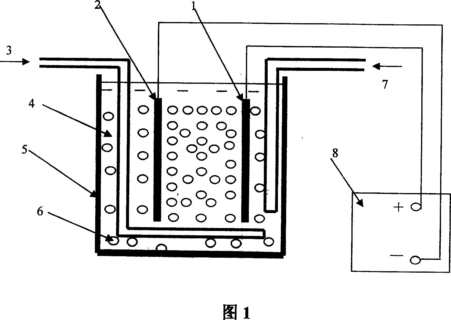
[0045] Nickel-based composite plating system: The nickel-based composite plating system is shown in Figure 1. The nickel-based composite plating solution 4 is prepared according to the composition of the above composite plating solution. Air 3 is introduced into the plating solution through a pipe, and the plating solution 4 is stirred under the action of a large number of air bubbles 6. In the rectangular plating tank 5, the plating solution in the plating tank is stir...

Embodiment 2

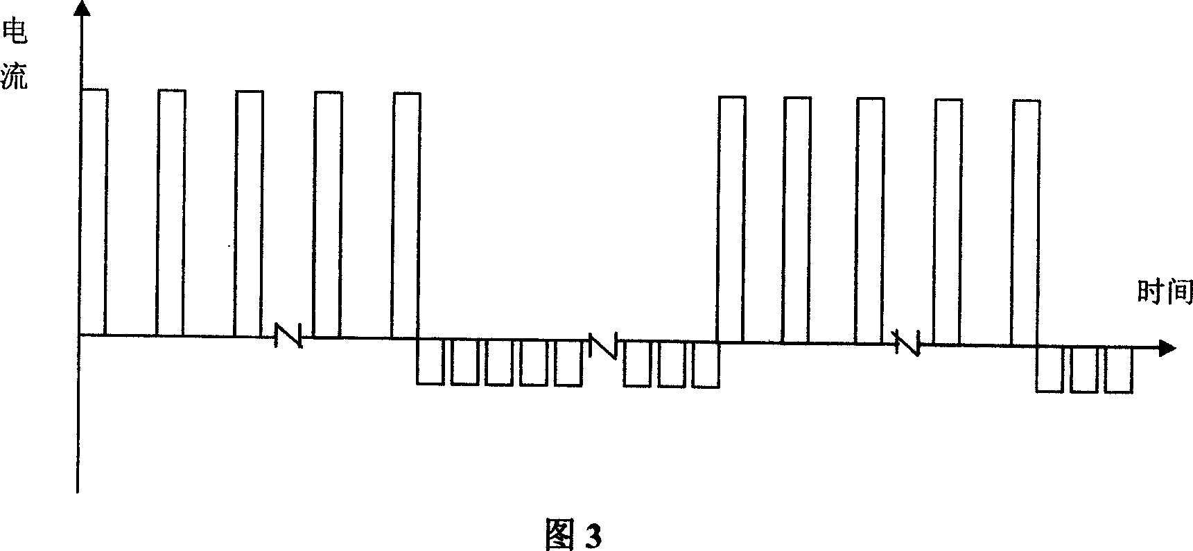
[0048] Example 2: Electroplating Ni-SiC-TiN nickel-based composite coating on the inner wall of the cylindrical mold using controlled current pulse electroplating

[0049] The composition of the composite plating solution is: Ni(BF 4 ) 2 500g / L

[0050] HBF 4 5g / L

[0051] H 3 BO 350g / L

[0052] Sodium lauryl sulfate 0.1g / L

[0053] Sodium polymethacrylate 15g / L

[0054] SiC (average particle size 1.2μm) 100g / L

[0055] TiN (average particle size 50nm) 5g / L

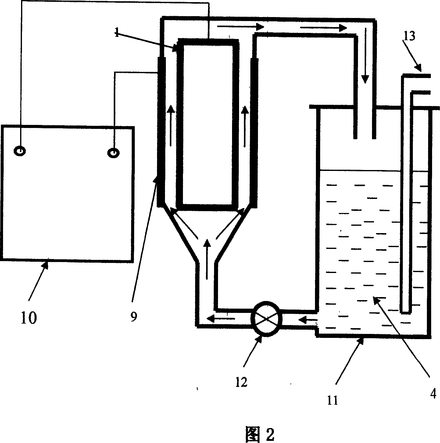
[0056] Nickel-based composite plating system: Figure 2 shows the use of a circulating pump 12 for liquid flow circulation, with a cylindrical mold 9 as a part of the plating tank, and pulse composite Ni-SiC-TiN coating on the inner surface of the cylindrical mold Schematic diagram of the composite coating device for composite coating. The nickel-based composite plating solution 4 is prepared according to the co...

Embodiment 3

[0059] Example 3: Ni-Co-Al composite plating on the inner wall of the square tube mold by voltage control 2 O 3 Nickel alloy base composite coating

[0060] Composite bath composition: Ni(NH 2 SO 3 ) 2 500g / L

[0061] NiCl 2 ·6H 2 O 25g / L

[0062] CoSO 4 50g / L

[0063] H 3 BO 3 55g / L

[0064] Mg 2 SO 4 50g / L

[0065] Lauric acid diacetamide 5g / L

[0066] Al 2 O 3 Nano particles (particle size d=50nm) 30g / L

[0067] Nickel alloy-based composite plating system: Figure 4 shows Ni-Co-Al electroplating on the inner surface of the square tube mold 14 under the condition of mechanical stirring. 2 O 3 Schematic diagram of a nickel alloy-based composite coating device. A stirrer 15 is used to mechanically stir the composite plating solution, the square tube-shaped crystallizer 14 is connected to the negative electrode of the DC power sup...


PUM

PropertyMeasurementUnit
Particle sizeaaaaaaaaaa

Abstract

The invention discloses a composite coating material and preparing method and equipment in the metallurgical conticaster crystallizer, which is composed of nickel-based composite material or nickel alloy composite material, which consists of base metal and large scale of particle or fiber in the base with polyphase structure, wherein the DC composite plating or composite pulse plating equipment is composed of plating power, plating groove, nickel anode or nickel alloy anode, metallurgical conticaster crystallizer, stirring device, liquid circulating device, heating and temperature-controlling device.

Description

Technical field [0001] The invention belongs to the field of surface technology, and particularly relates to a composite coating material used in the mold of a metallurgical continuous casting machine, and a manufacturing method and equipment. Background technique [0002] The metallurgical continuous casting machine mold has a wide range of applications in the metallurgical industry. At present, the mold of metallurgical continuous casting machine is generally made of copper alloy to ensure that the mold has good thermal conductivity. In view of the high temperature and wear characteristics of the metallurgical continuous casting machine mold, the metallurgical continuous casting machine mold is required to have excellent high temperature wear resistance. For this reason, people increase the service life of the metallurgical continuous casting machine mold by electroplating various types of metal coatings on the surface of the copper alloy continuous c...

Claims


Application Information

Patent Timeline
IPC IPC(8): C25D15/00B22D11/059
Inventor 王为
Owner CHENGDU SHENJIA MACHINERY MFG
Why Eureka
Try Eureka