
High-voltage frequency changing standard transducing power unit

A high-voltage frequency conversion and streaming power technology, which can be applied to the conversion equipment with intermediate conversion to AC, the conversion equipment without intermediate conversion to AC, and the conversion of DC power input to DC power output. It can solve the performance degradation and interference of high-voltage inverters The frequency spectrum bandwidth increases and the spatial distribution of interference energy increases, so as to achieve the effect of strong anti-deformation ability and high installation accuracy

Inactive Publication Date: 2007-03-07
ROCKWELL AUTOMATION CONTROL SOLUTIONS (HARBIN) CO LTD
View PDF0 Cites 26 Cited by
  • Summary
  • Abstract
  • Description
  • Claims
  • Application Information

AI Technical Summary

Problems solved by technology

But the electromagnetic operating environment of the power unit is getting worse and worse
With the increase of total voltage level and total output power, the spatial distribution of interference energy inside each standard power unit increases, the aperiodicity of time distribution increases, the spectral bandwidth of interference frequency increases, and the number of emission interference sources increases correspondingly. Its harsh electromagnetic compatibility environment seriously affects the normal operation of the power converter unit, reducing the performance and stability of the high-voltage inverter
[0007] At present, in the high-voltage inverter based on the principle of multi-voltage unit series voltage source, both internationally and domestically, attention is paid to power and heat dissipation for its power conversion unit, and there is no technical solution specifically for electromagnetic compatibility and standardization

Method used


Image

  • High-voltage frequency changing standard transducing power unit
  • High-voltage frequency changing standard transducing power unit
  • High-voltage frequency changing standard transducing power unit

Examples


Embodiment Construction

[0057] The present invention is described in more detail below in conjunction with accompanying drawing example:

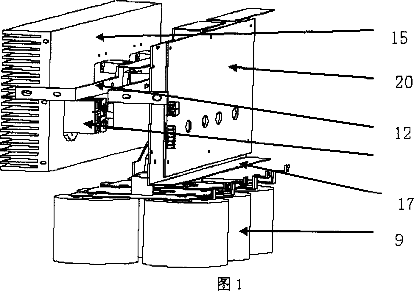
[0058] In conjunction with accompanying drawing 1, it is the key point of the present invention is the technical scheme of innovative electrical, electronic, structure, that is, "the capacitor array group is vertically arranged at the bottom of the unit, the radiator is vertically arranged on the side, and the control board is arranged on the other side. A shielding plate is arranged between the control board and the power device.The power device is arranged on the surface of the heat sink and is electrically connected with copper tape.

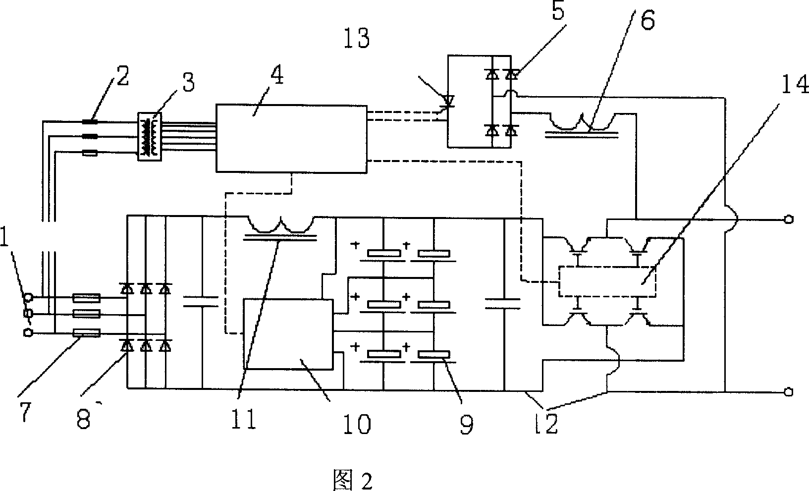
[0059] In conjunction with accompanying drawing 2, it is the principle wiring diagram of the present invention, and it is that power frequency alternating current power source (1) inserts main circuit insurance (7) and control circuit insurance (2), inserts full-bridge diode from main circuit insurance (7) (8), the cable of the d...


PUM


Abstract

This invention provides one high voltage transducer power unit, which comprises shell, function parts, control board, capacitor array and dissipation part, wherein, capacitor array is put on unit bottom; dissipation device is distributed on one side of capacitor array and other side with control board; there is shield board between control board and power parts with power parts on dissipation surface to connect parts through copper band.

Description

(1) Technical field [0001] The invention relates to a power electronic commutation device, specifically a system for realizing power conversion in a high-voltage frequency converter of the multi-level unit series voltage source type, and is called a commutation power unit in engineering. (2) Background technology [0002] my country's motor design concept and technology were learned from the Soviet Union in the 1950s, leaving a large margin in industrial design, and the power utilization rate of the system is low during operation. There is a great demand for energy saving in the application of high-voltage frequency converters in the power market. [0003] According to the national report "Research on the Ways and Countermeasures of Motor Speed ​​Control Technology Industrialization", 66% of China's total power generation is consumed on motors. At present, the total installed capacity of motors in China has exceeded 400,000 megawatts, and high-voltage motors account for abo...

Claims


Application Information

Patent Timeline
IPC IPC(8): H02M1/00H02M3/28H02M3/315H02M3/06H05K7/02H05K7/20
Inventor 李凯白德芳丁兆国周维来刘志强
Owner ROCKWELL AUTOMATION CONTROL SOLUTIONS (HARBIN) CO LTD
Learn More