Humidity controller

A technology of humidity control and heat exchanger, which is applied in the direction of air conditioning system, separation method, heating method, etc. It can solve the problems of affecting indoor comfort, the noise of the humidity control device entering the room, and the occurrence of noise, so as to achieve compact design and reduce ventilation pressure Loss, the effect of reducing the power load

Inactive Publication Date: 2010-05-12
DAIKIN IND LTD
View PDF9 Cites 0 Cited by
  • Summary
  • Abstract
  • Description
  • Claims
  • Application Information

AI Technical Summary

Problems solved by technology

[0010] However, in the above-mentioned conventional humidity control device, in order to regenerate the adsorbent, it is necessary to switch the circulation direction of the refrigerant in the refrigerant circuit every time, and noise is generated every time.
Therefore, the noise generated by the humidity control device may enter the room and affect the comfort of the room

Method used


Image

  • Humidity controller
  • Humidity controller
  • Humidity controller

Examples


Embodiment Construction

[0071] Embodiments of the present invention will be described below with reference to the drawings. The following embodiments are preferable illustrations in nature, and the present invention does not limit the scope of their applicability and use.

[0072] Embodiment 1 of the invention

[0073] Next, Embodiment 1 of the present invention will be described with reference to the drawings.

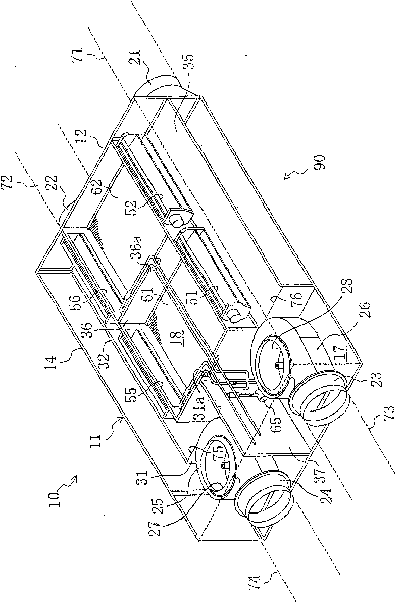
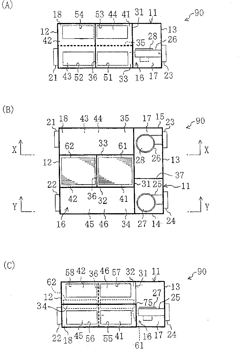
[0074] like Figure 1 ~ Figure 3As shown, the humidity control device 10 of this embodiment is used to dehumidify and humidify indoor air, and has, for example, a main body unit 90 disposed on the back of the indoor ceiling and a compressor unit 91 disposed outdoors. exist figure 2 Among them, (B) is a top view, (C) is a view from the Y direction, and (A) is a view from the X direction. In addition, the "right" and "left" described below are based on figure 2 prevail. figure 1 from the top right figure 2 A perspective view of the main body unit 90 in (B).

[0075] The humidity con...


PUM


Abstract

A humidity control system (10) is provided which includes a refrigerant circuit (60). The refrigerant circuit (60) includes first and second absorbent-supported heat exchangers (61, 62) and performs arefrigeration cycle by the circulation of refrigerant. In addition, in the refrigerant circuit (60), the circulation direction of refrigerant is reversible. The first and second heat exchangers (61,62) are disposed in a main casing (11) of a main unit (90). In the main unit (90), the distribution route of air is changed such that a first air stream is passed through either one of the first and second heat exchangers (61, 61) that is functioning as an evaporator while a second air stream is passed through the other heat exchanger that is functioning as a condenser. A compressor (63) of the refrigerant circuit (60) is disposed in a compressor unit (91) of separate installation from the main unit (90).

Description

technical field [0001] The invention relates to a humidity-regulating device for adjusting the humidity of air, in particular to a technique for regenerating and cooling an adsorbent by performing a refrigeration cycle. Background technique [0002] Conventionally, for example, as disclosed in Patent Document 1, there is known a humidity control device that uses an adsorbent and a refrigeration cycle to adjust the humidity of air. This humidity control device has 2 adsorption units. Each adsorption unit includes a mesh container filled with adsorbent and a refrigerant tube passing through the mesh container. The refrigerant pipes of each adsorption unit are connected to a refrigerant circuit that performs a refrigeration cycle. The humidity control device is provided with a damper for switching the air sent to each adsorption unit. [0003] During the operation of the humidity control device, the compressor of the refrigerant circuit is operated, and a refrigeration cycle...

Claims


Application Information

Patent Timeline
Patent Type & Authority Patents(China)
IPC IPC(8): F25B29/00B01D53/26F24F3/14F25B13/00
CPCF24F3/1411F24F3/1429
Inventor 藪知宏成川嘉則
Owner DAIKIN IND LTD
Why Eureka
Try Eureka