Cell tensile loader

A technology for loading devices and cells, applied in measuring devices, instruments, scientific instruments, etc., can solve the problems of inability to realize microscopic observation of cells, unintuitive cell deformation, uneven deformation, etc., and achieve convenient self-adjustment and cell stretching process. Smooth, well-consistent results

Inactive Publication Date: 2007-03-21
CHONGQING UNIV
View PDF1 Cites 22 Cited by
  • Summary
  • Abstract
  • Description
  • Claims
  • Application Information

AI Technical Summary

Problems solved by technology

The advantage of this loading instrument is that the control operation is completed by the CPU, and the cells are stretched or compressed in different forms through a stepping motor. However, the main problems of this loading instrument are: 1. The beam is between the four supporting points The deformation of the cell is uneven, which will inevitably lead to uneven defo

Method used


Image

  • Cell tensile loader
  • Cell tensile loader

Examples


Embodiment 1

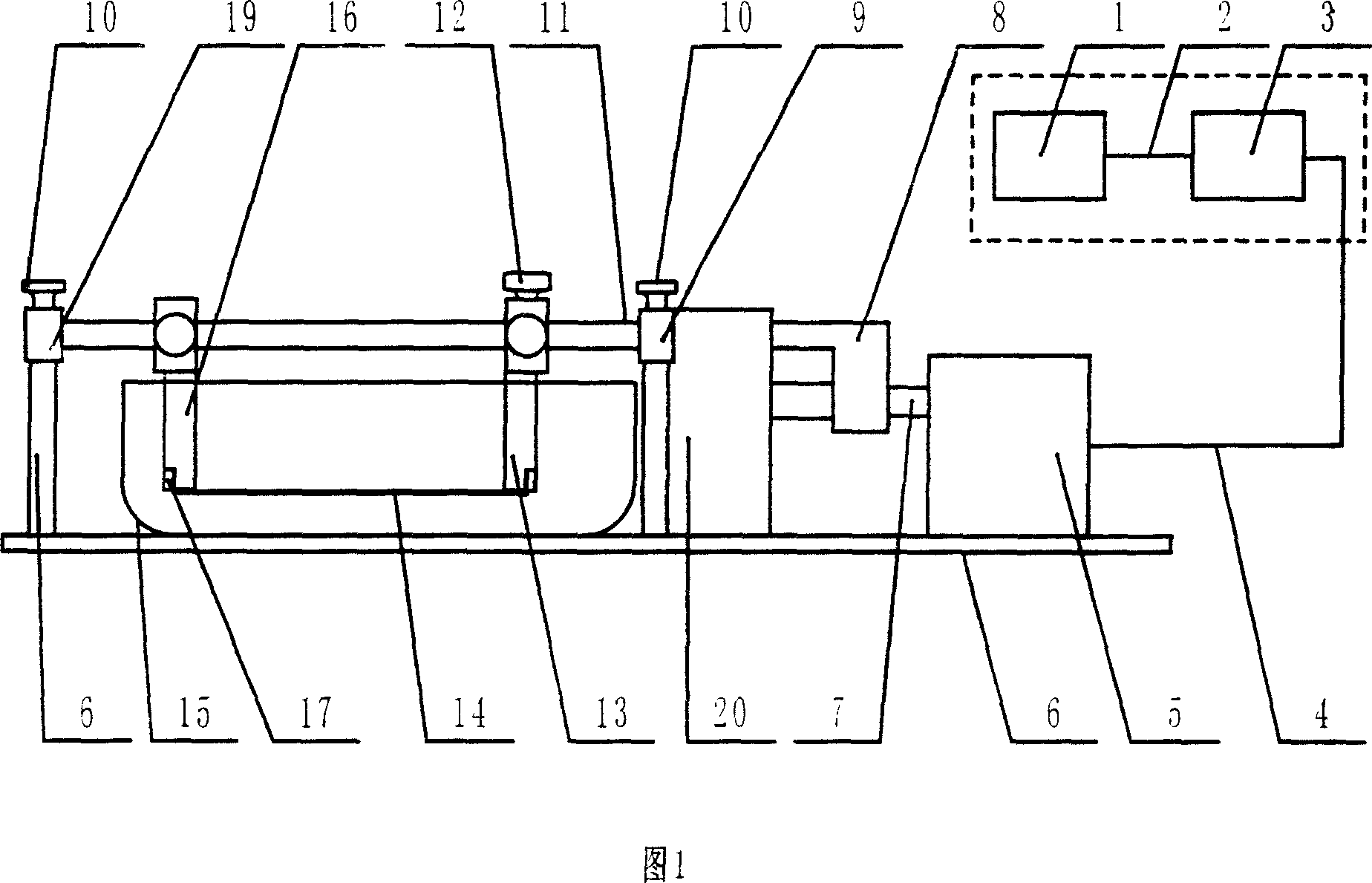
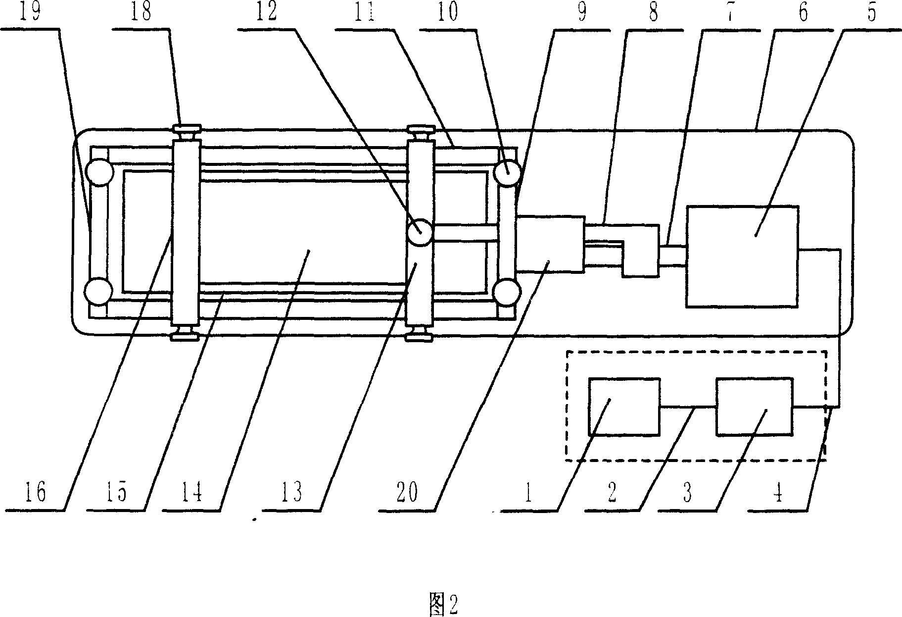
[0011] As shown in Figures 1 and 2, a cell stretching and loading device mainly includes a frame 6, a power system, a transmission system and a stretching movement part. The power system is mainly composed of a controller 1, a driver 3, and a stepping motor 5. The controller 1 is a computer, and the controller 1 outputs control signals through a program to control stretching frequency, stretching amplitude, and stretching form. The driver 3 is a power amplifier for outputting signals from the controller 1 so as to drive the stepper motor 5 to rotate to provide power for the device. The transmission system is mainly composed of a lead screw 7 and a pull rod 8, which transmits the rotational power of the stepping motor 5 to the sliding bracket 13 for horizontal and linear motion, so as to load and stretch the cells. The stretching movement part is mainly composed of a sliding bracket 13, a fixed bracket 16, a guide rod 11, a front guide rod block 9 and a rear guide rod block 19...

Embodiment 2

[0013] As shown in Figures 1 and 2, a cell stretching and loading device mainly includes a frame 6, a power system, a transmission system and a stretching movement part. The power system is mainly composed of a controller 1, a driver 3, and a stepping motor 5. The controller 1 is a single-chip microcomputer, and the controller 1 outputs control signals through a program to control stretching frequency, stretching amplitude, and stretching form. The driver 3 is a power amplifier for outputting signals from the controller 1 so as to drive the stepper motor 5 to rotate to provide power for the device. The transmission system is mainly composed of a lead screw 7 and a pull rod 8, which transmits the rotational power of the stepping motor 5 to the sliding bracket 13 for horizontal and linear motion, so as to load and stretch the cells. The stretching movement part is mainly composed of a sliding bracket 13, a fixed bracket 16, a guide rod 11, a front guide rod block 9 and a rear g...

Embodiment 3

[0015]As shown in Figures 1 and 2, a cell stretching and loading device mainly includes a frame 6, a power system, a transmission system and a stretching movement part. The power system is mainly composed of a controller 1, a driver 3, and a stepping motor 5. The controller 1 is a programmable controller, and the controller 1 outputs control signals through a program to control stretching frequency, stretching amplitude, and stretching form. The driver 3 is a power amplifier for outputting signals from the controller 1 so as to drive the stepper motor 5 to rotate to provide power for the device. The transmission system is mainly composed of a lead screw 7 and a pull rod 8, which transmits the rotational power of the stepping motor 5 to the sliding bracket 13 for horizontal and linear motion, so as to load and stretch the cells. The stretching movement part is mainly composed of a sliding bracket 13, a fixed bracket 16, a guide rod 11, a front guide rod block 9 and a rear guid...


PUM


Abstract

A kind of cell pulls to stretch to add to carry device, involve a medical science experiment instrument in of the cell mechanics add to carry device. The invention mainly includes a machine, motive system and spreads to move system and pulls to stretch sport part. Motive system mainly from controller, actuator, tread to constitute into the electrical engineering; Spread to move the system main grenadine and pull pole composing; Pull to stretch sport part mainly from glide a support, fix support, direction pole, pioneer pole piece and behind lead a pole piece composing. Because the invention has and pull and stretch process to the cell steady, the cell is subjected to dint even, the ability accurate control pulls and stretches range and frequency, pulling and stretching distance can the convenience regulates within the scope of 0~60 mm, can make under same condition of the experiment have good consistency etc. characteristics, so the invention can used to a medical science experiment the cell mechanics of the instrument and add and carry device extensively, is the ideal which carries on mechanics incitement and responds to a research to the living creature organization and the cell in the biomechanics and add and carry device.

Description

technical field [0001] The invention belongs to the technical field of biomechanical engineering, in particular to a cell mechanical loading device in a medical experiment instrument. technical background [0002] With the development of tissue engineering and biomedical engineering, cell mechanics and tissue engineering have become frontier subjects in the development of modern biology. In order to study the effects of various physical and biochemical factors on human tissues, it is necessary to solve the problem of how to mechanically load cells. In the existing cell loading device, such as the patent of "Four-Point Bending Cell Mechanics Loading Apparatus" with publication number CN1425905A, it is disclosed that the stepper motor executes the commands of the CPU, thereby driving the punching head to run various speeds, displacements, stamping The head deforms the beam between the four support points of left and right symmetry, so that the surface area of ​​the beam chang...

Claims


Application Information

Patent Timeline
IPC IPC(8): G01N33/00G01N3/00C12Q1/02
Inventor 邓兆祥王红兵邓波
Owner CHONGQING UNIV
Why Eureka
Try Eureka