
Silicon wafer prealigning device

A pre-alignment, silicon wafer technology, applied in electrical components, semiconductor/solid-state device manufacturing, circuits, etc., can solve problems such as low precision, complex mechanism, silicon wafer damage, etc., to improve the accuracy of mechanical motion, simplify the control system, Satisfy the effect of positioning accuracy

Inactive Publication Date: 2007-03-28
DALIAN UNIV OF TECH
View PDF3 Cites 20 Cited by
  • Summary
  • Abstract
  • Description
  • Claims
  • Application Information

AI Technical Summary

Problems solved by technology

The disadvantages of this method are: because the mechanical mechanism directly contacts the silicon wafer, it is easy to cause damage to the silicon wafer; the precision is low, and it can only meet the equipment above 0.35μm, which cannot meet the accuracy requirements of the whole machine. It can only be said to be a reservation for the silicon wafer. bit, not strictly pre-aligned; the process is complex and takes a long time; the mechanism is complex
Although this pre-alignment method has a simple structure, the control system and algorithm are very complex, and the requirements for the positioning and grasping accuracy of the robot end effector are also very strict.
The patent CN1787200A applied by Tsinghua University focuses on a control method for optical pre-alignment of silicon wafers, but does not introduce its equipment structure

Method used


Image

  • Silicon wafer prealigning device
  • Silicon wafer prealigning device
  • Silicon wafer prealigning device

Examples


Embodiment Construction

[0047] Specific embodiments of the present invention will be described in detail below in conjunction with technical solutions and accompanying drawings.

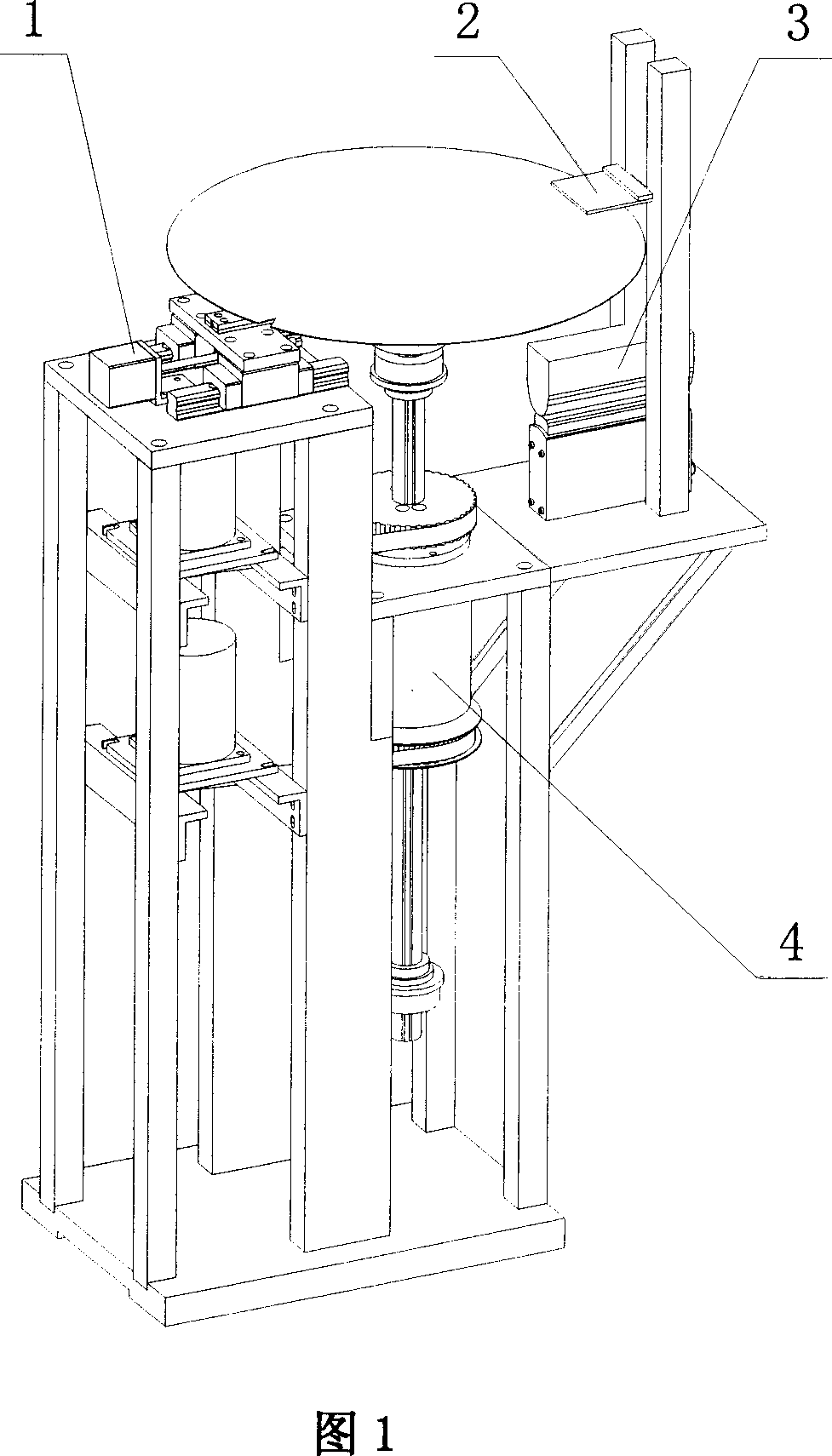
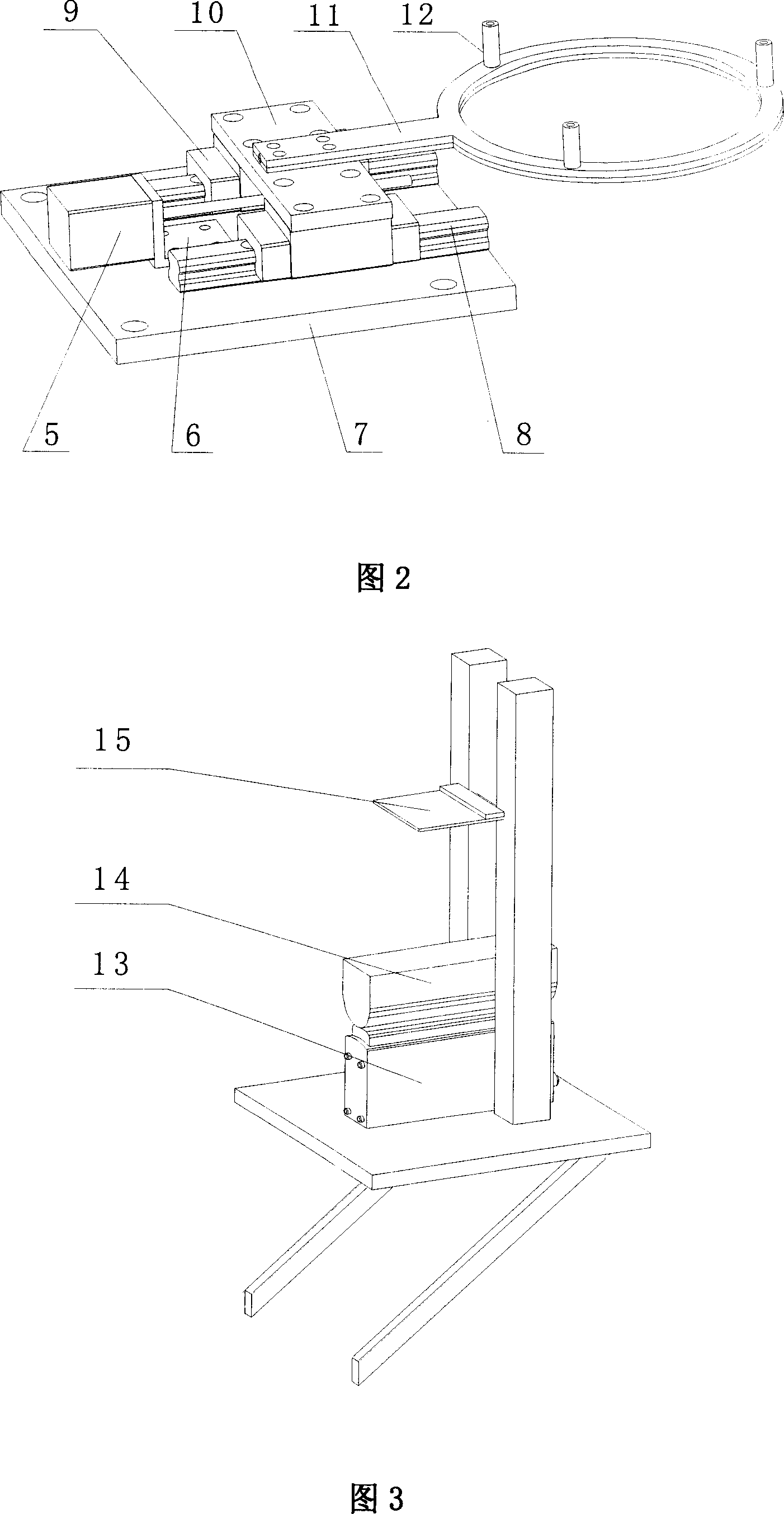
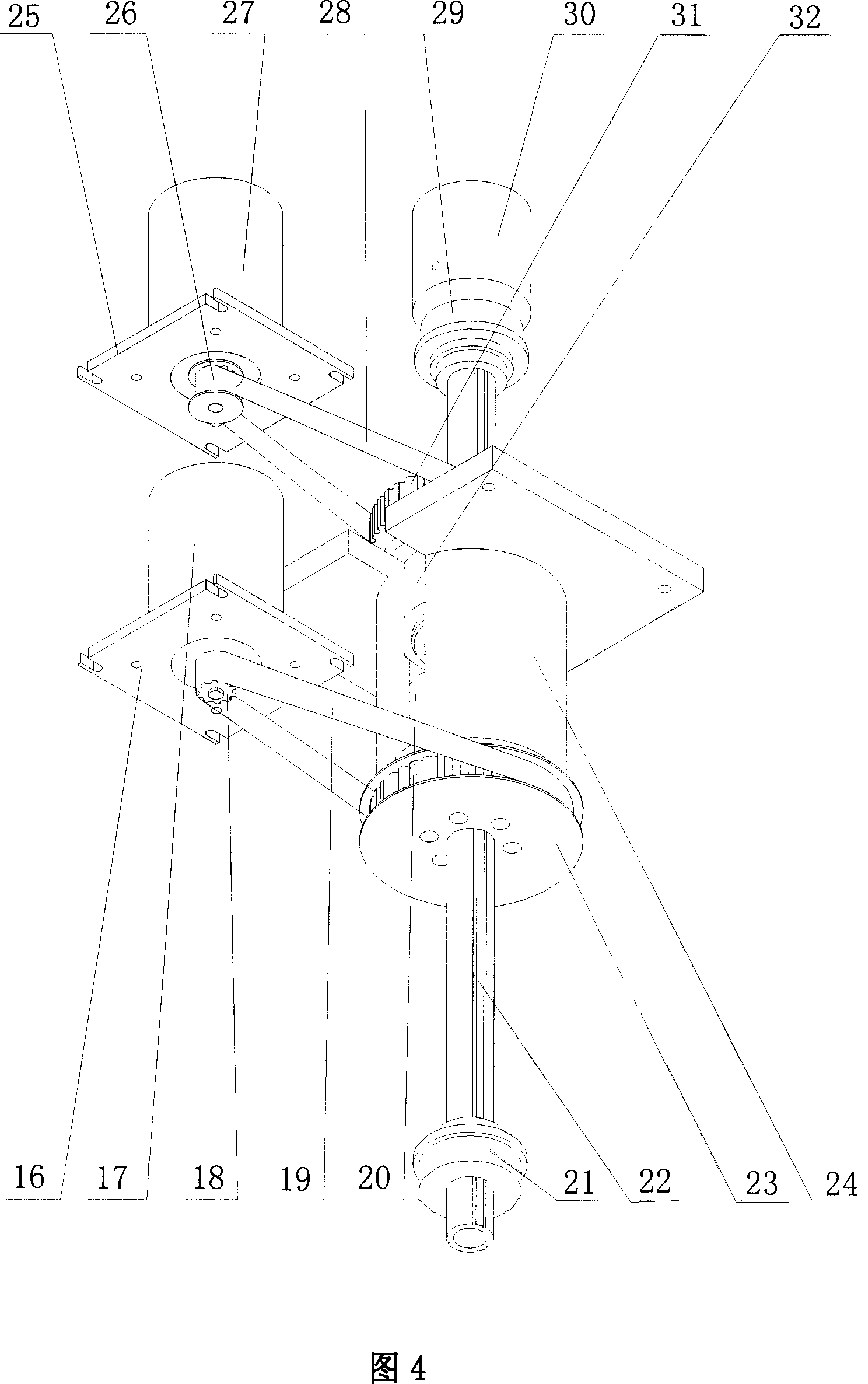
[0048]The working process of the present invention is as follows: the silicon wafer robot puts the silicon wafer on the cylindrical wafer holder 30, the TCD1500C linear array image sensor 15 detects that the silicon wafer has reached the pre-alignment device, the TCD sensor sends a signal to the motor control card, and simultaneously Trigger the vacuum generator to make the cylindrical wafer stage 30 vacuum absorb the silicon wafer. The motor control card controls the rotating stepper motors 17 and 27 to move synchronously and reversely, and the synchronous toothed large belt pulleys 23 and 31 respectively drive the ball spline nut 20 and the ball screw nut 32 to rotate synchronously and reversely, and the ball screw spline is on the ball spline The decoupling movement of the nut 20 and the ball screw nut 32 drives the sili...


PUM


Abstract

The pre alignment apparatus includes horizontal center align unit, TCD detection unit, unit for projecting light, chip load unit, data conversion and control unit. The align unit is in use for adjusting deviation in Y direction of silicon chip. The TCD detection unit is in use for detecting positions of edge, cutting edge, or notch of silicon chip. The unit for projecting light is in use for transmitting parallel beam. The chip load unit is in use for rotating and lifting silicon chip. The data conversion and control unit is in use for receiving, transforming, and sending signal of light intensity of TCD detection unit as well as controlling movement of step motor. Using optical detection instrument and cooperated simple mechanism, the method realizes positioning silicon chip including geometric center, cutting edge or notch in high accuracy. The method can compensate position error of silicon occurred in transmission procedure. Features are: simple algorithm and low cost.

Description

technical field [0001] The invention belongs to the technical field of integrated circuit equipment manufacturing, and particularly relates to a silicon chip pre-alignment device and method thereof, which are used for positioning the geometric center and trimming (or notch) of the silicon chip. Background technique [0002] Silicon wafer pre-alignment device is a kind of device for integrated circuit manufacturing, which can automatically detect and accurately locate the geometric center of silicon wafer and the trimming (or notch) position during silicon wafer processing, integrating machinery, electronics, optics, computer and other multi-disciplinary high-precision alignment devices. [0003] Since the processing technology has higher requirements on the positioning accuracy of the silicon wafer than the transmission accuracy of the silicon wafer robot, the silicon wafer robot must first place the silicon wafer on the pre-alignment device before processing the silicon waf...

Claims


Application Information

Patent Timeline
Patent Type & Authority Applications(China)
IPC IPC(8): H01L21/68
Inventor 丛明杜宇张传思孔祥吉沈宝宏金立刚
Owner DALIAN UNIV OF TECH
Learn More