Dust collecting device

A technology of dust collection device and dust collection part, which is applied in cleaning devices, vacuum cleaners, applications, etc., can solve the problems of motor drive noise, high motor drive noise, large motor, etc., to reduce conveying force, reduce conveying resistance, Effect of reducing power consumption

Inactive Publication Date: 2007-03-28
SANYO ELECTRIC CO LTD
View PDF3 Cites 5 Cited by
  • Summary
  • Abstract
  • Description
  • Claims
  • Application Information

AI Technical Summary

Problems solved by technology

[0009] However, in the manual type dust collector, the distance between the suction port of the floor suction unit and the dust collection part on the chassis is long, so there is a need for a strong suction force, and the motor for dust collection needs to be large. such problem
[0010] In addition, in Patent Documents 1 and 3, the motor for dust collection is continuously driven. Therefore, the driving noise of the motor continues to be generated, and the power consumption is high. It is continuously driven, so there is a problem of poor dust collection efficiency
In addition, in Patent Document 2, the dust on the floor swept by the rotating brush is directly conveyed to the dust collection unit, so there is a problem that a relatively large motor must be used, the driving noise of the motor is high, and the power consumption is also high.

Method used


Image

  • Dust collecting device
  • Dust collecting device
  • Dust collecting device

Examples


Embodiment approach 1

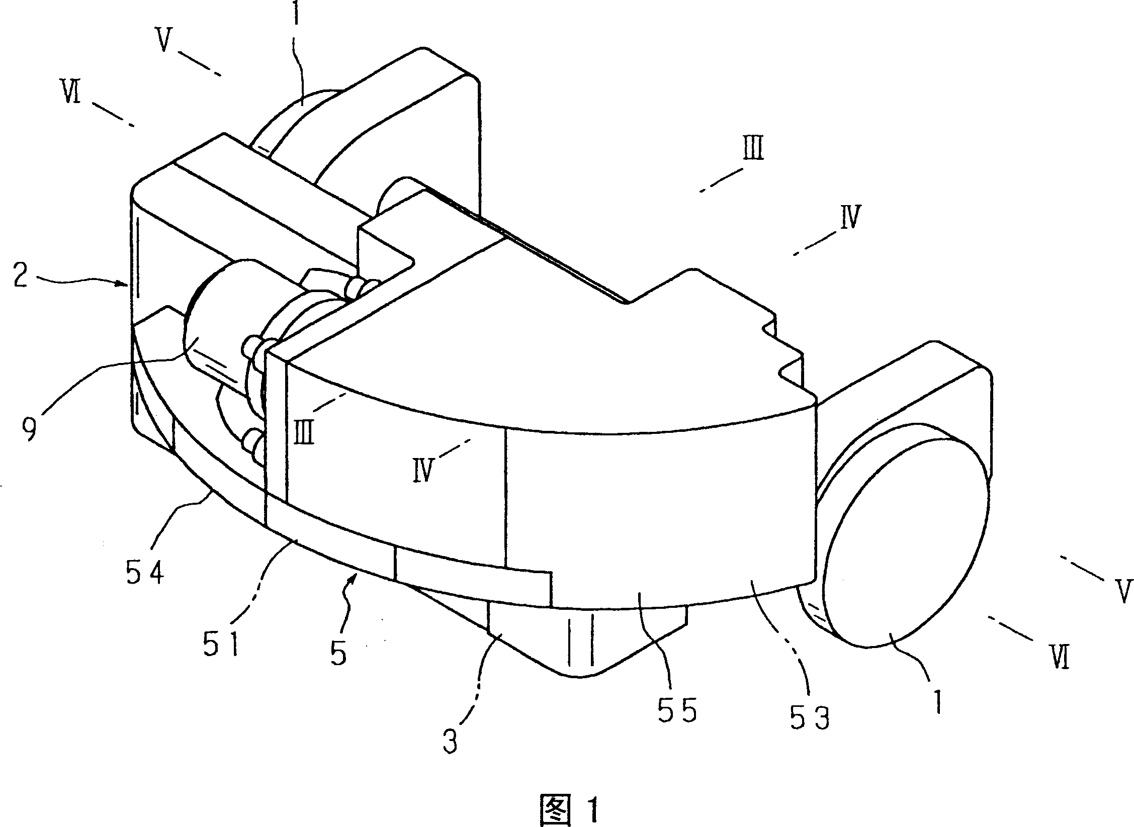
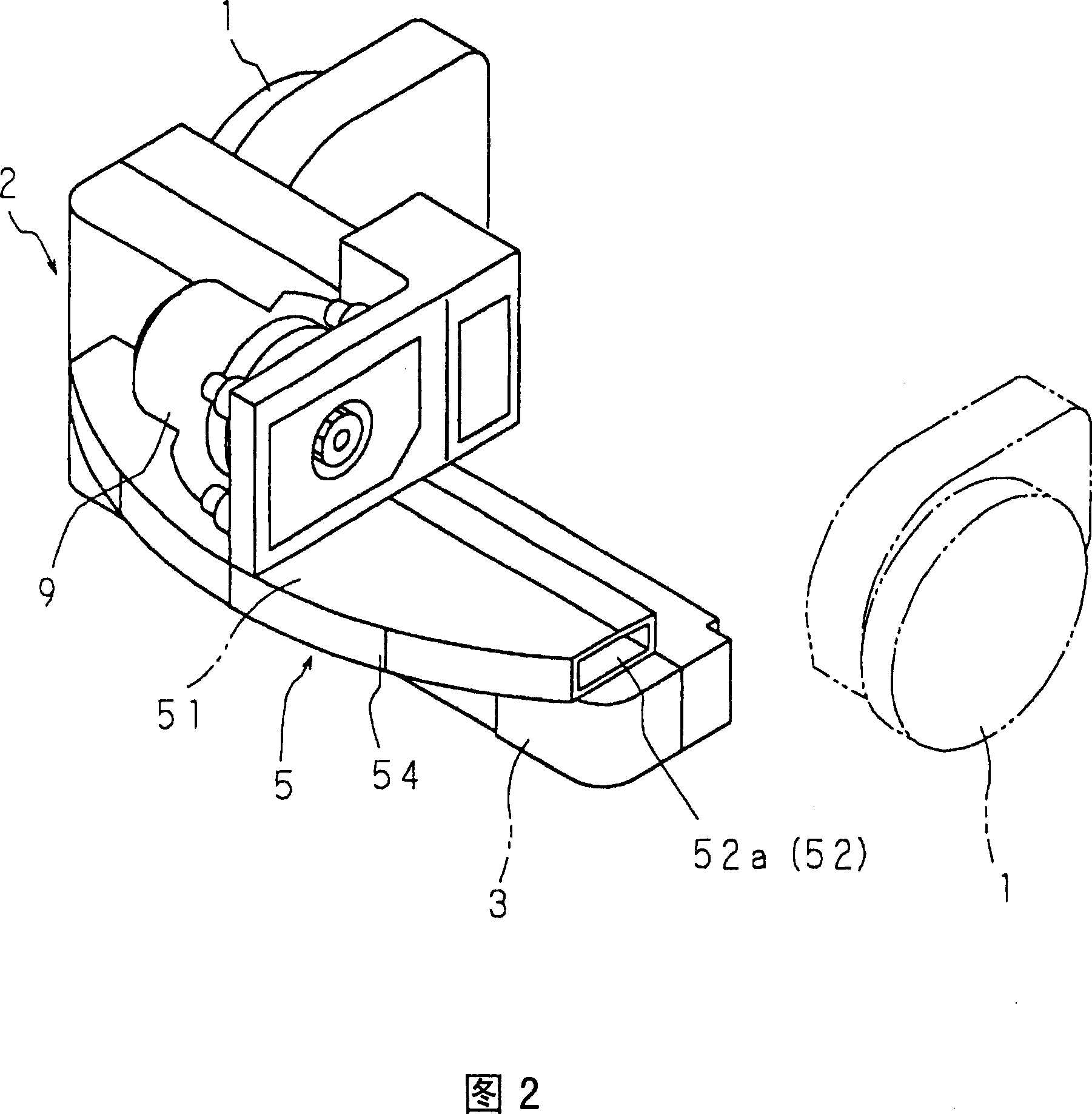
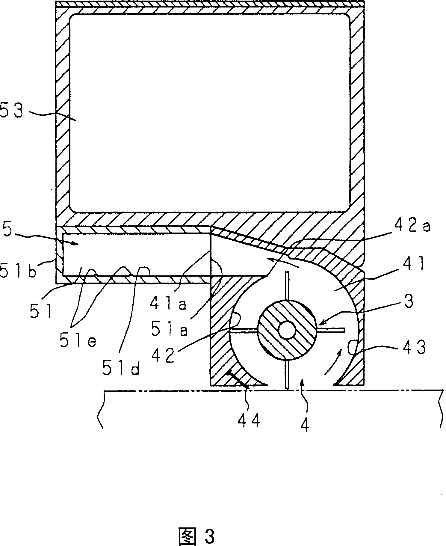
[0122] Fig. 1 is a perspective view showing the configuration of Embodiment 1 of the dust collector of the present invention, Fig. 2 is a perspective view showing a state in which the secondary chamber of the dust collecting unit is removed, and Fig. 3 is an enlarged cross-section taken along line III-III of Fig. 1 Fig. 4 is an enlarged sectional view of the IV-IV line of Fig. 1, Fig. 5 is an enlarged sectional view of the V-V line of Fig. 1, Fig. 6 is an enlarged sectional view of the VI-VI line of Fig. 1, and Fig. 7 shows that after a part is removed Fig. 8 is a plan view showing the structure of the dust collecting part, Fig. 9 is a rear view showing the structure of Embodiment 1, and Fig. 10 is a side view showing the structure of Embodiment 1.

[0123] The dust collecting device shown in Fig. 1 is a self-propelled dust collecting device as a cleaning robot, which includes: a trolley 2 supported by a plurality of traveling wheels 1; The dust part 4; the dust collecting par...

Embodiment approach 2

[0134] 11 is a cross-sectional plan view showing the structure of Embodiment 2 of the dust collector of the present invention, FIG. 12 is a longitudinal sectional side view showing the structure of the main part, FIG. 13 is a cross-sectional plan view showing the structure of the main part, and FIG. 14 It is a longitudinal sectional side view showing the configuration of main parts, FIG. 15 is a plan view with parts omitted, and FIG. 16 is a schematic perspective view of main parts.

[0135] This dust collector has basically the same structure as Embodiment 1. However, as in Embodiment 1, instead of having a communication path 52 on one side in the longitudinal direction of the dust collecting port 51a of the primary chamber 51, it is configured to include a dust collecting The communication path 57 opened on the opposite side of the port 51 a further includes a housing 58 in which the secondary chamber 53 is detachably provided, and the operation body 11 that locks the housing...


PUM


Abstract

A dust collecting device capable of reducing the transfer power required to transfer dust, downsizing a transfer means, saving power consumption, and reducing noise from the transfer means. The dust collecting device is provided with a dust take-in section having a rotary brush (3), and a dust collecting section (5) for collecting dust taken in from the dust take-in section. The dust collecting section (5) has a primary chamber (51) for storing dust combed up by the rotation of the rotary brush (3), and a secondary chamber (53) communicating with the primary chamber through a communication passage. An electric fan (9) is installed in order to intermittently transfer dust in the primary chamber (51) into the secondary chamber (53).

Description

technical field [0001] The invention relates to a dust collecting device having a rotating brush in a dust suction part. Background technique [0002] As dust collectors, there are known a manual type that sweeps while holding a suction tool for the floor and moving it manually, and a self-propelled type that has a traveling trolley driven by an electric motor. The manual dust collecting device is provided with a tubular floor suction unit, a chassis connected to the floor suction unit and having a dust collection unit and a dust collection motor, and the dust collection unit and the floor suction unit are connected to each other by driving the motor. A suction airflow is generated to suck dust on the floor through the suction port of the floor suction unit. [0003] Self-propelled dust collectors are disclosed in Patent Document 1, Patent Document 2, and Patent Document 3. The dust collecting device in Patent Document 1 is configured to include: a dust collecting unit hav...

Claims


Application Information

Patent Timeline
Patent Type & Authority Applications(China)
IPC IPC(8): A47L11/18A47L11/202A47L7/02A47L9/10A47L11/33
CPCA47L7/02A47L11/4019A47L2201/00A47L11/4077A47L9/106A47L11/4041A47L11/33A47L11/4013A47L11/4044A47L11/18A47L11/202
Inventor 中川龙幸广濑达也
Owner SANYO ELECTRIC CO LTD
Why Eureka
Try Eureka