Purification method for gas mixture

A gas mixture and mixture technology, which is applied in chemical instruments and methods, liquefaction, inorganic chemistry, etc., can solve the problems that the exhaust gas cannot be burned at the bottom and is no longer flammable.

Inactive Publication Date: 2007-04-04
LINDE AG
View PDF2 Cites 4 Cited by
  • Summary
  • Abstract
  • Description
  • Claims
  • Application Information

AI Technical Summary

Problems solved by technology

These methods lead to additional technical complexity (turbine, pressure regulator and additional heat exchange path), but also with increased investment costs and increased nitrogen

Method used


Image

  • Purification method for gas mixture

Examples


Embodiment Construction

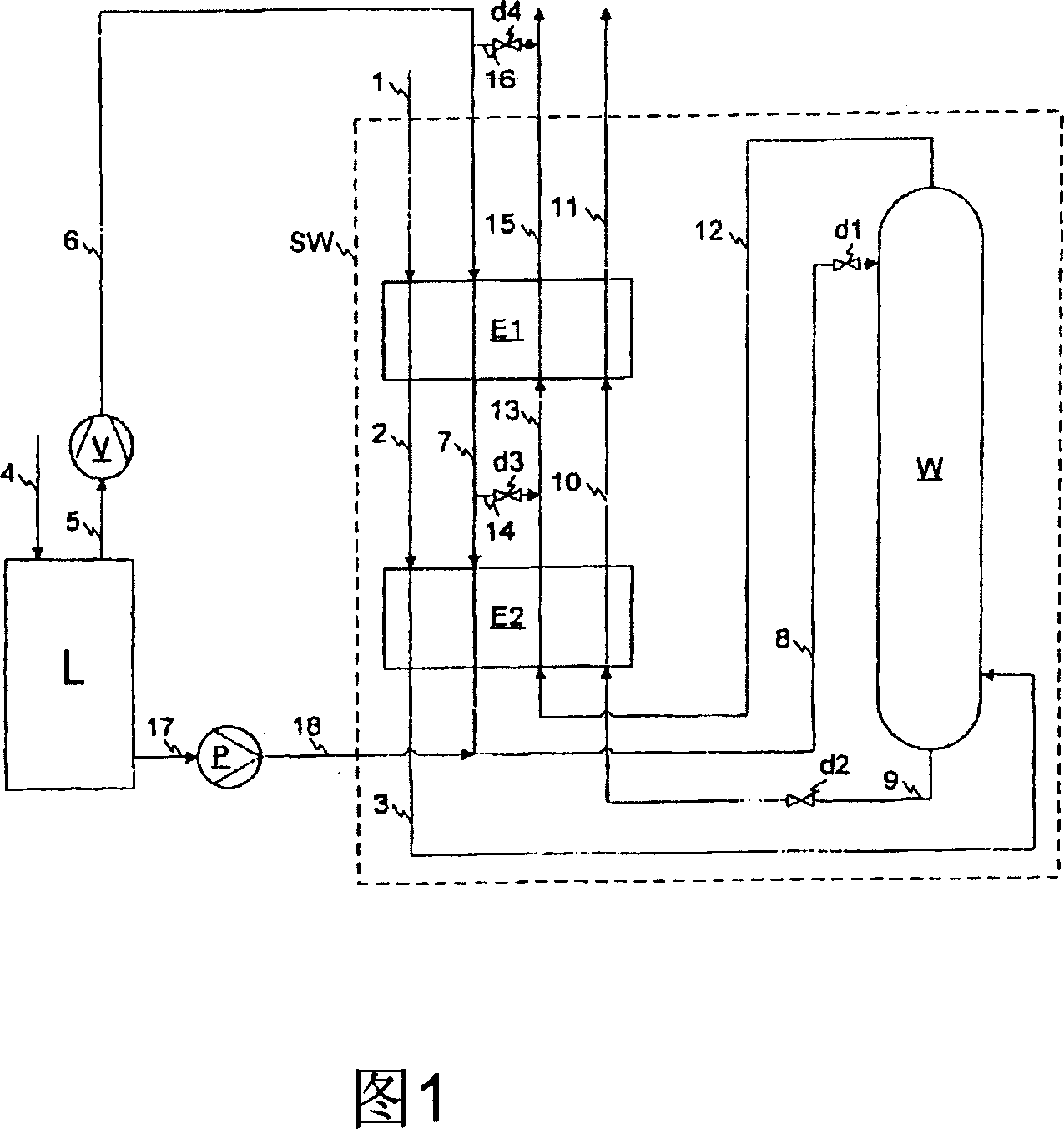
[0015] The exemplary embodiment relates to a process for the production of a feedstock gas for the synthesis of ammonia, wherein the synthesis gas consists essentially of hydrogen, carbon monoxide and methane and, where applicable, argon and nitrogen, which is purified by cryogenic nitrogen scrubbing. To remove unwanted substances (especially carbon monoxide, which is harmful to ammonia synthesis catalysts, but also methane and argon).

[0016] Synthesis gas can be prepared with maximum freedom from water and carbon dioxide in PO-reactors, steam reformers or autothermal reformers and introduced via line 1 at a pressure of about 30 bar and a temperature of about 20 °C into the In the heat exchanger E1 in the low temperature nitrogen scrubber (SW), there, like in the heat exchanger E2 into which the synthesis gas is approached via line 2, it is cooled by means of the process liquid stream to be heated. The cooled synthesis gas is then introduced into the scrubber W via line 3 . ...


PUM


Abstract

The method involves obtaining a part of the washing column of supplied nitrogen liquid and deep-frozen from a cryogenic air decomposer. The liquid nitrogen obtained from a cryogenic air decomposer is combined with a further liquid nitrogen stream and supplied together with the washing agents of the washing column.

Description

technical field [0001] The present invention relates to a method of purifying a gas mixture at elevated pressure by cryogenic scrubbing with liquid nitrogen in a scrubber column, wherein nitrogen fed to the scrubber column is used as scrubbing and cooling source. Background technique [0002] On an industrial scale, cryogenic gas scrubbing with liquid nitrogen (nitrogen scrubbing) is used in particular for the production of feed gas for the synthesis of ammonia. The gas treated in nitrogen scrubbing is raw syngas, which is usually produced from charged hydrocarbons by vaporization, autothermal reforming, or partial oxidation, followed by cooling to remove moisture by condensation, and before nitrogen scrubbing, finally Unwanted species such as water vapor and acid gases are removed by a combination of scrubbing (e.g. methanol or amine scrubbing) and absorption. In nitrogen scrubbing, the synthesis gas, which contains in particular hydrogen, carbon monoxide and methane and, ...

Claims


Application Information

Patent Timeline
IPC IPC(8): F25J3/00
CPCC01B3/506C01B2203/068C01B2203/046F25J3/0223F25J2205/30F25J3/04521F25J2270/904F25J3/04587C01B3/025F25J3/0276F25J2210/42C01B2203/047
Inventor 格罗布·萨沙兰德斯·赫维希
Owner LINDE AG
Why Eureka
Try Eureka