Wave front-distortion laser device in corrected resonance cavity
A wavefront distortion and resonant cavity technology, applied to the structure/shape of optical resonators, lasers, laser components, etc., can solve the problems of small deformation and insufficient correction of wavefront distortion in the cavity, and achieve low cost , Improve the correction effect, the effect of simple structure
- Summary
- Abstract
- Description
- Claims
- Application Information
AI Technical Summary
Problems solved by technology
Method used
Image
Examples
Embodiment 1
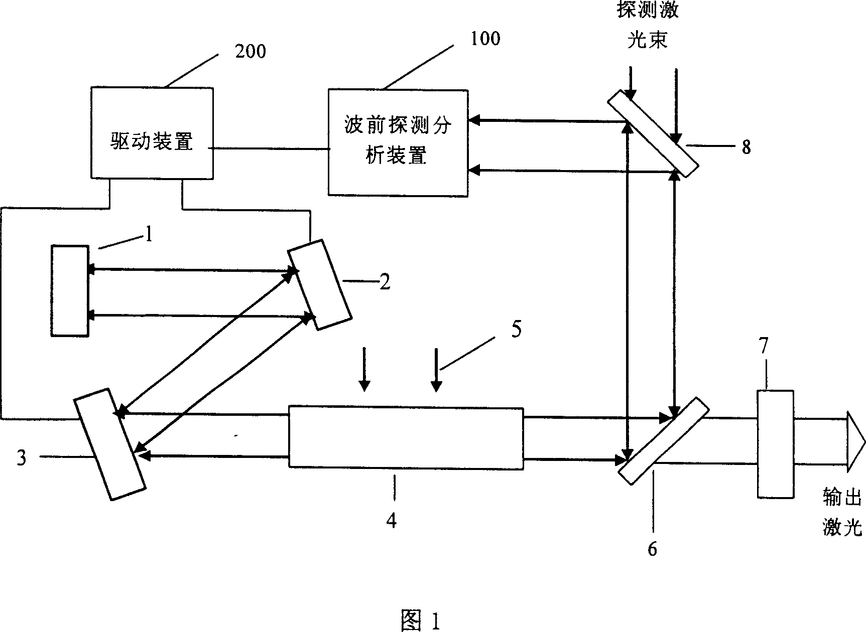
[0035] According to the optical path in Figure 1, a solid-state laser that uses an intracavity adaptive system to correct intracavity wavefront distortion is fabricated. The laser crystal 4 adopts Nd:YAG and is side-pumped by the pump light 5, and the laser device outputs 1064nm laser. The detection laser beam with a wavelength of 632.8nm is reflected by the mirror 6 and then enters the laser resonant cavity. The detection laser beam is coaxial with the oscillation beam in the cavity, and the diameters of the two beams are the same. The detection laser beam passes through the pumped laser crystal 4, is reflected by the tilting mirror 2 and the deformable mirror 3, and reaches the cavity mirror 1; the detection laser beam reaching the cavity mirror 1 is reflected by it, passes through the laser crystal 4 and returns along the original path, and the detection light Two passes through the laser crystal 4. When the returned detection beam passes through the beam splitter 8, a par...
Embodiment 2
[0038] According to the optical path in Figure 1, a solid-state laser that uses an intracavity adaptive system to correct intracavity wavefront distortion is fabricated. Its optical circuit diagram and each device are the same as those in Embodiment 1, except that the pumping method is end-pumping.
[0039] Adjust the cavity mirrors 1 and 7 to make the resonator output 1064nm laser light, and use the type and size of the aberration obtained by the wavefront detection and analysis device 100. The wavefront detection and analysis device 100 outputs a control signal to the drive device 200, thereby rotating the tilting mirror 3 to correct The oblique aberration in the laser crystal changes the shape of the reflective surface of the deformable mirror 2, and corrects other aberrations in the laser crystal except for the oblique aberration, so as to improve the beam quality and output power of the laser output from the laser.
Embodiment 3
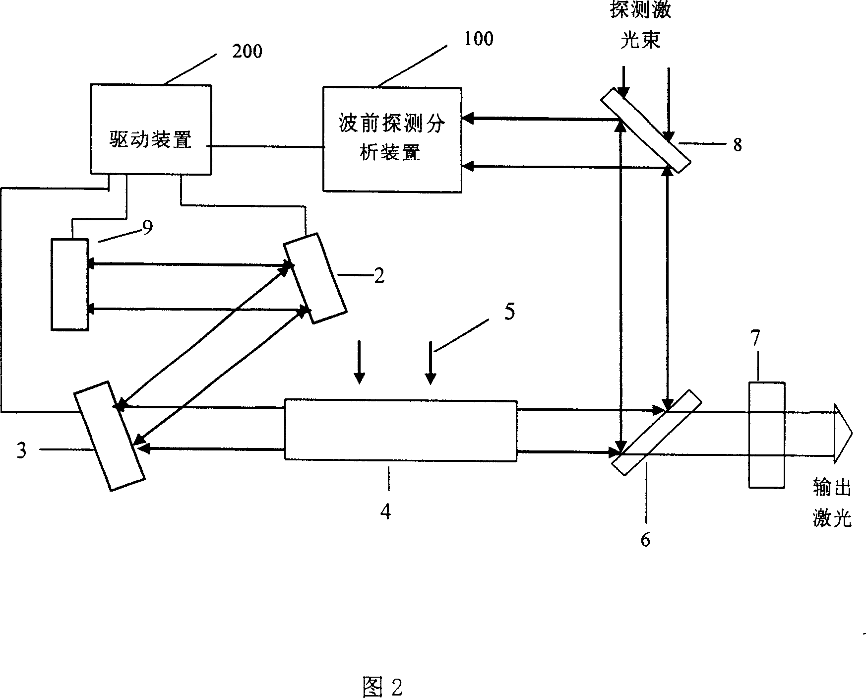
[0041] According to the optical path in Figure 2, a solid-state laser that uses an intracavity adaptive system to correct intracavity wavefront distortion is fabricated. Wherein, according to Embodiment 1, the cavity mirror 1 is removed and replaced with an increased second deformable mirror 9; the tilt mirror 3 and the two deformable mirrors 2 and 9 are all connected to the drive device 200; the laser crystal 4 adopts Nd:YVO 4 , is side-pumped by the pumping light 5 , and the laser device outputs 1342nm laser light. The cavity mirror 7 selects the flat mirror surface to be coated with a 1342nm partly transparent film, and the transmittance is 10%, and the other side is plated with an anti-reflection film of 1064nm; 632.8nm high-reflection coating; one side of the beam splitter 8 close to the laser crystal 4 is coated with a 1342nm anti-reflection coating and a 632.8nm total reflection coating, and the other side is coated with a 1342nm anti-reflection coating.
[0042] Adjus...
PUM
 Abstract
Description
Claims
Application Information
 - R&D
- Intellectual Property
- Life Sciences
- Materials
- Tech Scout
- Unparalleled Data Quality
- Higher Quality Content
- 60% Fewer Hallucinations
Browse by: Latest US Patents, China's latest patents, Technical Efficacy Thesaurus, Application Domain, Technology Topic, Popular Technical Reports.
© 2025 PatSnap. All rights reserved.Legal|Privacy policy|Modern Slavery Act Transparency Statement|Sitemap|About US| Contact US: help@patsnap.com


