
Optical member, method of manufacturing the same, and image display device applying the same

A technology for optical components and manufacturing methods, which is applied to optical elements, optics, nonlinear optics, etc., can solve the problems of industrial waste and poor effective area utilization, and achieve improved utilization efficiency, improved area effective utilization, and ready for easy effect

Inactive Publication Date: 2007-04-11
NITTO DENKO CORP
View PDF3 Cites 4 Cited by
  • Summary
  • Abstract
  • Description
  • Claims
  • Application Information

AI Technical Summary

Problems solved by technology

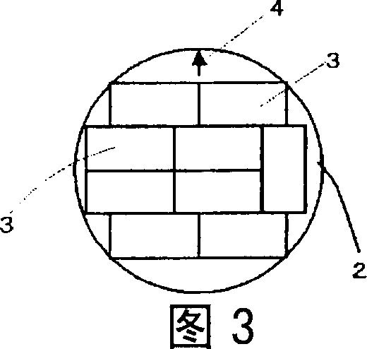
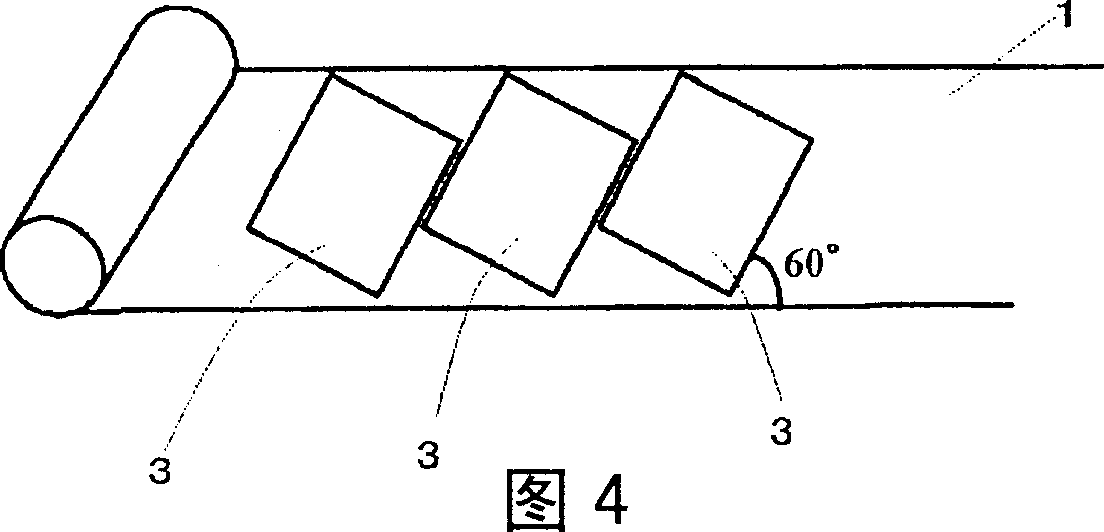
In this way, the above-mentioned polarizing plate is cut so that the optical axis becomes a predetermined direction, and is used in a liquid crystal display device, etc., so there is a problem that the effective utilization of the area is not good, and a large amount of industrial waste is generated.
In order to make such changes and adjustments, it is necessary to temporarily stop the flow of the process for processing, so it takes a lot of effort and time

Method used


Image

  • Optical member, method of manufacturing the same, and image display device applying the same
  • Optical member, method of manufacturing the same, and image display device applying the same
  • Optical member, method of manufacturing the same, and image display device applying the same

Examples


Embodiment 1

[0118] (production of polarizer)

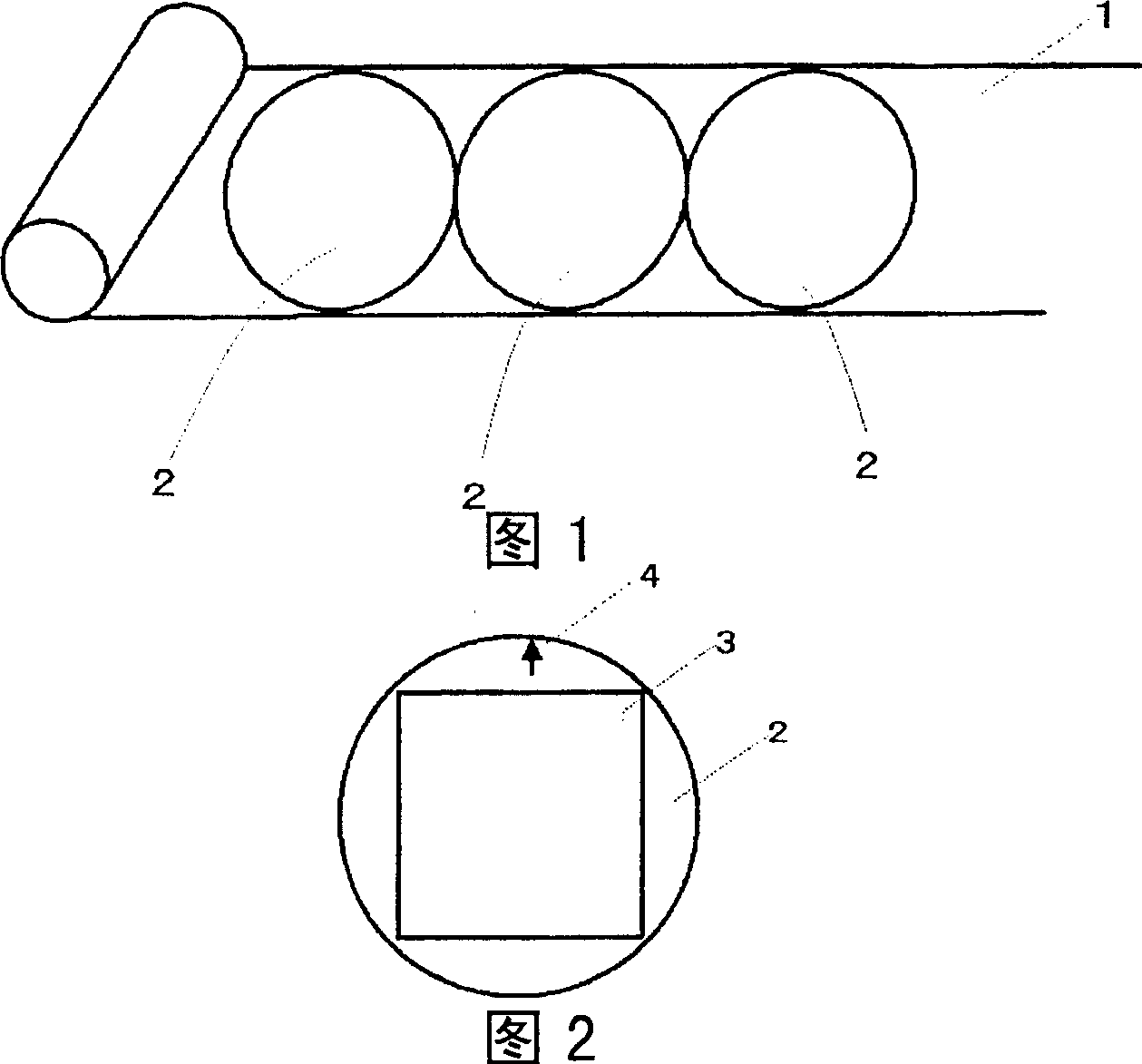
[0119] A polarizer having a width of 55 cm and a thickness of 30 μm was obtained by impregnating iodine into a long polyvinyl alcohol (PVA) film and stretching it. Triacetylcellulose (TAC) films having a thickness of 80 μm were bonded to both sides of the polarizer via a PVA-based adhesive layer having a thickness of about 1 μm after drying to form a polarizer. A release film made of a polyester (PE) film with a thickness of 25 μm treated with a silicone-based release agent and an acrylic adhesive film with a thickness of 20 μm after drying were bonded to one side of the polarizer through the above-mentioned adhesive layer. agent layer as a polarizer. As shown in FIG. 1 , 100 sheets of this polarizing plate were punched out using a perfectly circular Thomson blade with a diameter of 480 mm.

[0120] (Manufacturing of phase plate)

[0121] Similarly, a long polycarbonate (PC) film with a width of 52 cm was produced by uniaxially stretching ...

Embodiment 2

[0125] A polarizing plate and a retardation plate having a diameter of 480 mm were produced in the same manner as in Example 1, and a circular optical member having an optical axis angle of 40° after bonding was produced.


PUM

PropertyMeasurementUnit
thicknessaaaaaaaaaa
thicknessaaaaaaaaaa
thicknessaaaaaaaaaa

Abstract

A highly versatile optical member machined into a circular shape for eliminating the effect of optical axis unique to optical members is disclosed which is capable of facilitating stock control without lowering production efficiency. An optical member having a higher degree of freedom in design can be provided by employing such a production method wherein a long optical member is machined into a circular shape and then the circular optical member is machined into a desired shape so that the optical axis can be adjusted finely even after machining of the long optical member.

Description

technical field [0001] The present invention relates to an optical member used in an image display device such as a liquid crystal display (LCD), an electroluminescence display (ELD), a plasma display (PD), and a field emission display (FED: Field Emission Display). Manufacturing method. In addition, the present invention also relates to an image display device using the optical member. Background technique [0002] Thin optical members used in image display devices, such as polarizers and retardation plates used in liquid crystal display devices, have traditionally been formed by attaching an adhesive layer or an adhesive layer to an elongated optical member (optical film). In the state where the release film or the like is attached and the adhesive layer or the adhesive layer is protected by the release film, or in the original state of the optical member without the adhesive layer or the adhesive layer, it is punched into customer requirements Rectangular-shaped optical...

Claims


Application Information

Patent Timeline
Patent Type & Authority Applications(China)
IPC IPC(8): G02B5/30G02F1/13363G02F1/1335
CPCG02B5/3083G02B5/305G02B5/30
Inventor 池田英雄石崎孝次伊藤稔北田和生
Owner NITTO DENKO CORP
Learn More