Photoetching equipment

A lithography equipment and lithography technology, applied in microlithography exposure equipment, optomechanical equipment, optics, etc., can solve problems such as the influence of exposure accuracy, improve the influence of exposure accuracy, improve alignment offset and light leakage, The effect of reducing the amount of change in the pattern

Inactive Publication Date: 2007-05-02
CHUNGHWA PICTURE TUBES LTD
View PDF0 Cites 3 Cited by
  • Summary
  • Abstract
  • Description
  • Claims
  • Application Information

AI Technical Summary

Problems solved by technology

In addition, since the robot arm 130 is close to the exposure device 160, the vibration generated by the operation of the robot arm 130 will also affect the exposure accuracy of the exposure device 160.

Method used


Image

  • Photoetching equipment
  • Photoetching equipment
  • Photoetching equipment

Examples


Embodiment Construction

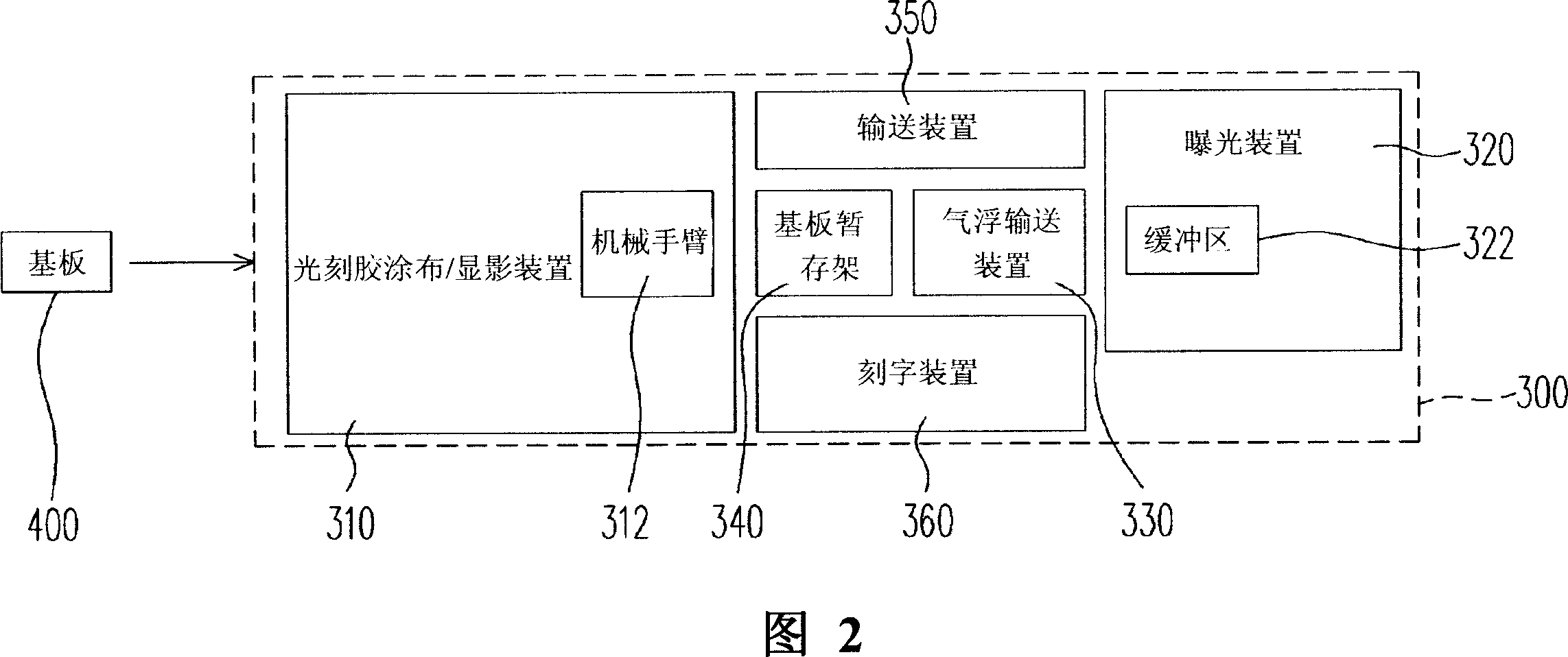
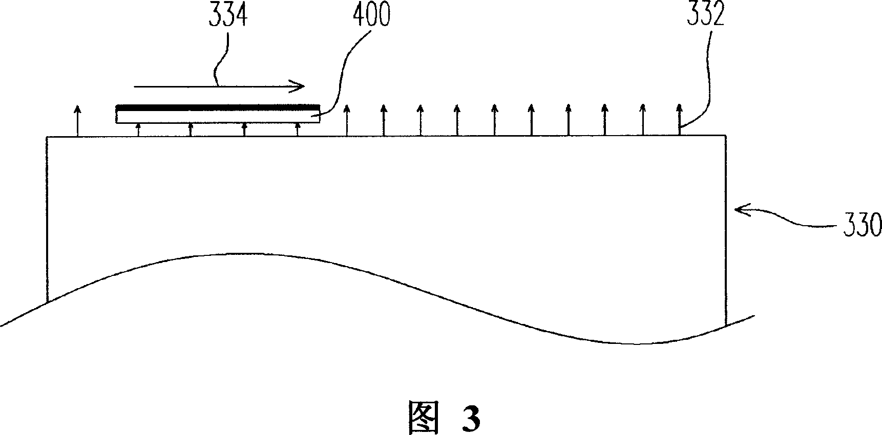
[0038] FIG. 2 is a schematic diagram of a lithographic apparatus according to a preferred embodiment of the present invention, and FIG. 3 is a schematic diagram of the air flotation conveying device in FIG. 2 . Please refer to FIG. 2 and FIG. 3 at the same time, the lithography apparatus 300 of this embodiment is suitable for performing a lithography process on a substrate 400 . The photolithographic equipment 300 includes a photoresist coating and developing device 310, an exposure device 320, and an air-floating conveying device 330, wherein the air-floating conveying device 330 is arranged between the photoresist coating and developing device 310 and the exposure device 320, and The air flotation transport device 330 is suitable for transporting the substrate 400 into the exposure device 320 . The lithography process using the lithography apparatus 300 will be described in detail later.

[0039] After the substrate 400 is sent to the photoresist coating and developing devi...


PUM


Abstract

A photo etching device is for a substrate which having a first temperature scope when it is moved out from photoresist coating as well as displaying unit, setting air float transfer unit between photoresist coating as well as displaying unit and exposing unit, driving base plate to said exposing unit by air float transfer unit, making air ejected out from air float transfer unit be the second temperature scope being part of the first temperature scope.

Description

technical field [0001] The present invention relates to a developing device, and in particular to a photolithographic device. Background technique [0002] Due to the increasing demand for displays, the industry is fully committed to the development of related displays. Among them, the cathode ray tube (Cathode Ray Tube) has been monopolizing the display market for many years due to its excellent display quality and technological maturity. However, due to the rise of the concept of green environmental protection, the characteristics of large energy consumption and large radiation, and the limited space for product flattening, it cannot meet the market demand for light, thin, short, small, beautiful and low power consumption. market trends. Therefore, thin film transistor liquid crystal displays (Thin Film Transistor Liquid Crystal Display, TFT-LCD) with superior characteristics such as high image quality, good space utilization efficiency, low power consumption, and no rad...

Claims


Application Information

Patent Timeline
Patent Type & Authority Applications(China)
IPC IPC(8): G03F7/00G03F7/20H01L21/00
Inventor 吴恒忠
Owner CHUNGHWA PICTURE TUBES LTD
Why Eureka
Try Eureka