Method for manufacturing powder used for pressing and manufacturing Fe-Si-Al magnetic core
A manufacturing method and technology for magnetic powder cores are applied in the field of manufacturing powder for pressing FeSiAl magnetic powder cores, which can solve the problems of unachieved magnetic permeability and achieve the effects of good formability and compaction.
- Summary
- Abstract
- Description
- Claims
- Application Information
AI Technical Summary
Problems solved by technology
Method used
Image
Examples
Embodiment 1
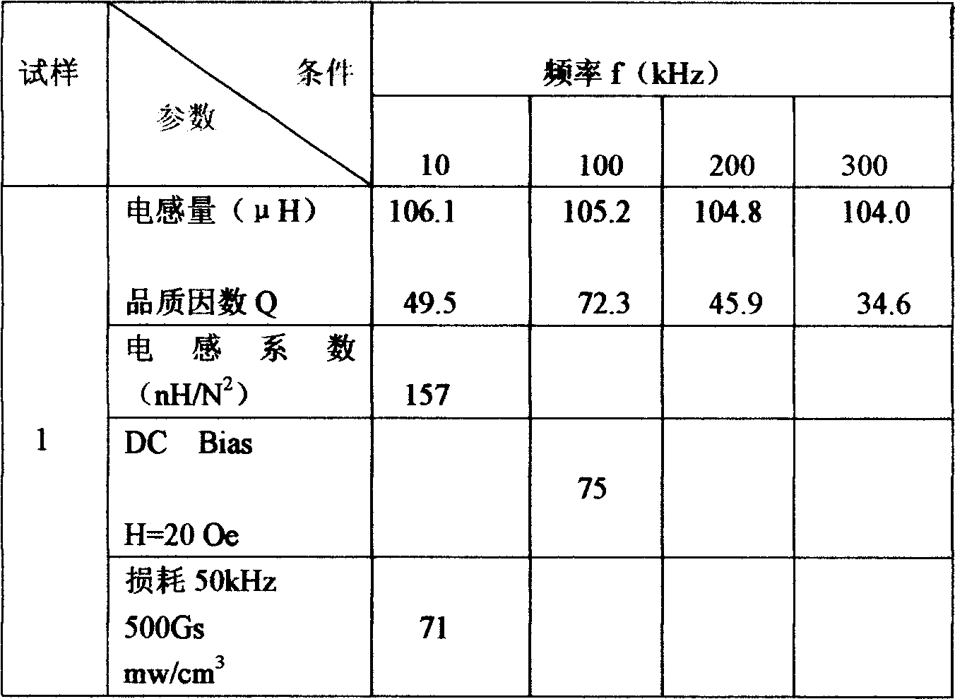
[0015] Put industrial pure iron, polysilicon, pure aluminum, metal manganese, and sponge titanium into a vacuum induction furnace with a nominal weight of 50 kg for smelting. Its chemical composition is 9.02% silicon, 6.48% aluminum, 0.18% manganese, 0.35% titanium, and the rest is Fe , C is 0.012%, O 2 is 90PPm, N 2 For alloy ingots ≤ 50PPm, the alloy ingots are broken into pieces below 30 mm by hammer crushing method, and then enter the jaw crusher to be broken into pieces below 3 mm, and then enter the high-efficiency vibrating ball mill to grind them into pieces less than 120 Purpose alloy powder. The alloy powder is placed in a box-type electric furnace with hydrogen protection and kept at 900±10°C for 4 hours for stress relief treatment. According to the weight percentage of particles less than 120 mesh to 200 mesh is 20, the weight percent of particles less than 200 mesh to 300 mesh is 60, and the rest is less than 300 mesh particles, passivation treatment is carried ...
Embodiment 2
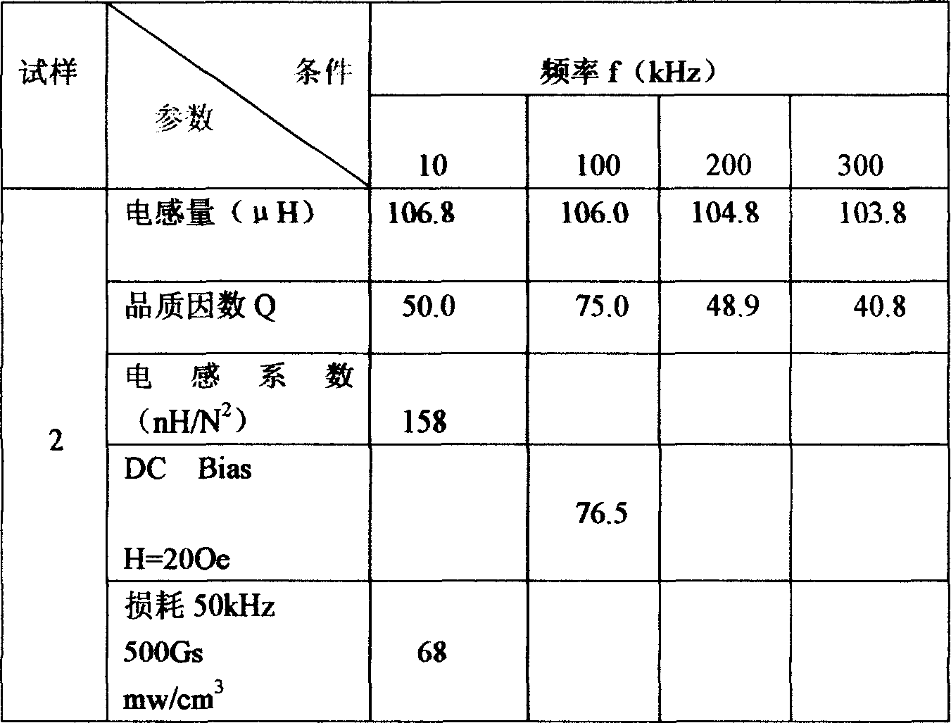
[0020] The manufacturing process is the same as in Example 1, the chemical composition of the alloy is 9.96% Si, 5.60% Al, 0.12% Mn, 0.55% Ti, 0.012% C, O 2 ≤0.010%, N 2 =40PPm, the remainder being Fe. The crushing method is the same as in Example 1. The stress relief treatment temperature is 1000°C for 2 hours, and the particle size ratio is: less than 120 mesh to 200 mesh accounts for 15%, less than 200 mesh to 300 mesh accounts for 60%, and the rest is fine powder less than 300 mesh. Powder passivation treatment, adding insulating agent, lubricant, release agent and mixing uniformly are the same as in Example 1, and its electromagnetic performance parameters are shown in Table 2:
[0021] Table 2 φ27.0 / φ14.7×11.20 φ0.5mm, 26Ts
[0022]
Embodiment 3
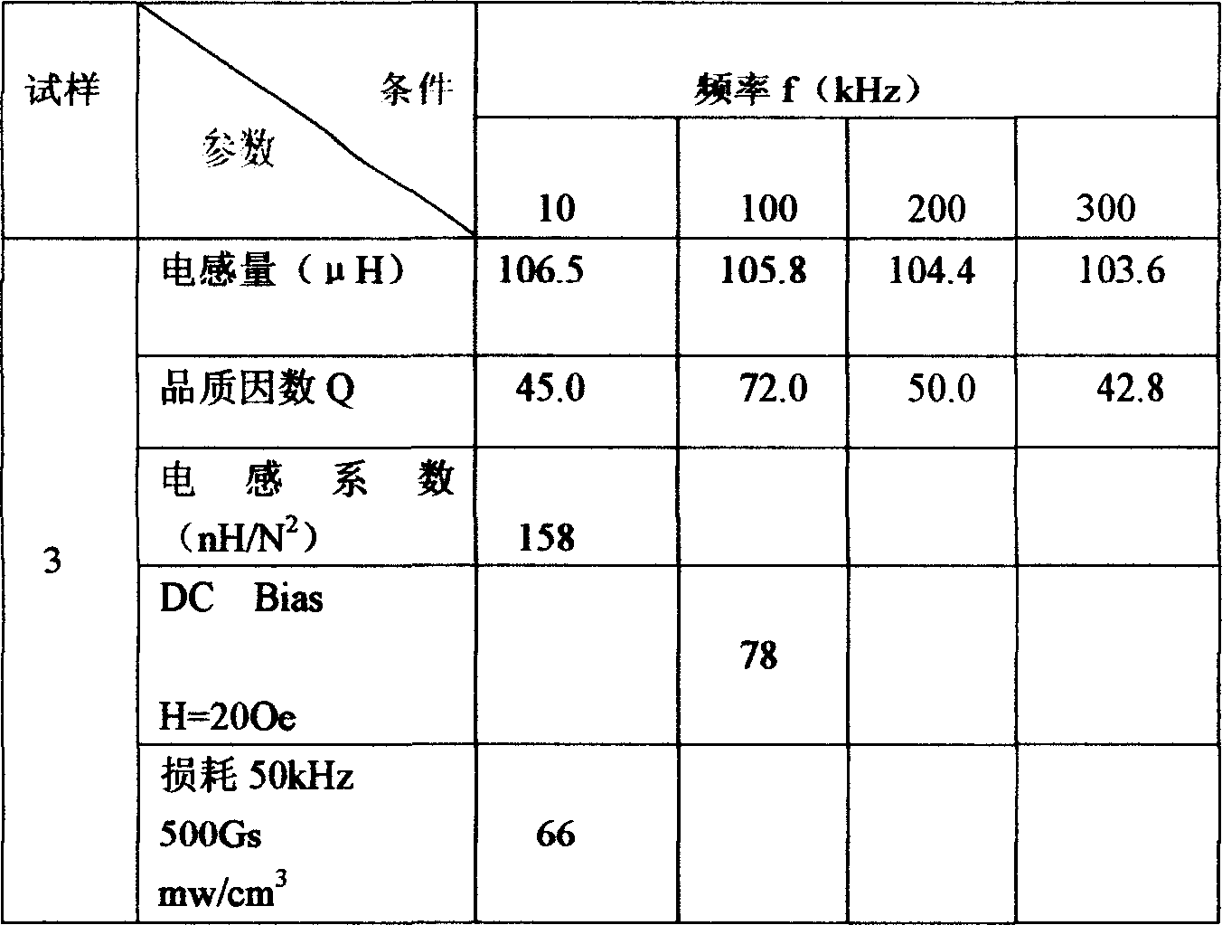
[0024] The manufacturing process is the same as in Example 1, the chemical composition of the alloy is 9.50% Si, 6.00% Al, 0.15% Mn, 0.45% Ti, 0.008% C, O 2 80PPm,N 2 40PPm, remaining is Fe, and crushing method is with embodiment 1, and stress relief treatment temperature is 950 ℃ of insulations for 3 hours, particle size proportioning is with embodiment 2, and operations such as powder passivation treatment are with embodiment 1. Its electromagnetic performance parameters are shown in Table 3:
[0025] Table 3 φ27.0 / φ14.7×11.20 φ0.5mm, 26Ts
[0026]
PUM
| Property | Measurement | Unit |
|---|---|---|
| coercivity | aaaaa | aaaaa |
Abstract
Description
Claims
Application Information
 - R&D
- Intellectual Property
- Life Sciences
- Materials
- Tech Scout
- Unparalleled Data Quality
- Higher Quality Content
- 60% Fewer Hallucinations
Browse by: Latest US Patents, China's latest patents, Technical Efficacy Thesaurus, Application Domain, Technology Topic, Popular Technical Reports.
© 2025 PatSnap. All rights reserved.Legal|Privacy policy|Modern Slavery Act Transparency Statement|Sitemap|About US| Contact US: help@patsnap.com


