Filter and cyanine compound

A filter and compound technology, applied in the fields of filter, optics, organic chemistry, etc., to achieve the effects of excellent light resistance and solubility, high molar absorption coefficient, and excellent heat resistance

Inactive Publication Date: 2007-05-23
NIPPON KAYAKU CO LTD
View PDF1 Cites 14 Cited by
  • Summary
  • Abstract
  • Description
  • Claims
  • Application Information

AI Technical Summary

Problems solved by technology

However, since antimony-containing compounds are hazardous substances, in recent years, in industrial fields where the use of heavy metals is restricted, especially in the field of electrical materials, compounds that do not contain heavy metals are expected.

Method used


Image

  • Filter and cyanine compound
  • Filter and cyanine compound
  • Filter and cyanine compound

Examples


Embodiment 1

[0092] Synthesis of compound 1

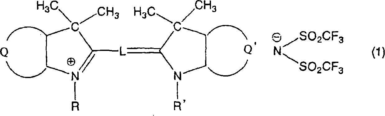
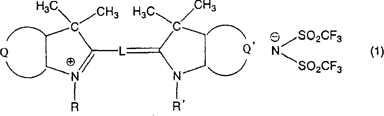
[0093] Mix 9.6 parts of 1,3,3-trimethyl-2-methyleneindoline with 10.6 parts of 1,3,3-trimethyl-2-formylmethyleneindoline, 17.6 parts of (bistrifluoromethanesulfonyl) shown in the formula

[0094]

[0095] Potassium imide was placed in 75 parts of acetic anhydride, boiled for 1 hour under reflux condensation, then cooled to room temperature, and the reaction solution was suction filtered to remove insoluble impurities. Then, 100 parts of water was dropped into the reaction solution, the precipitated crystals were suction filtered, 40 parts of methanol were added for recrystallization, washed with 5 parts of methanol, washed with water and dried to obtain 19.4 parts of the aforementioned compound 1. The spectral characteristics of the obtained compound 1 are as follows.

[0096] The maximum absorption wavelength is 544nm (in methanol)

[0097] Molar absorptivity 133000 (in methanol)

Embodiment 2

[0099] Synthesis of compound 3

[0100] 14.9 parts of 4,5-benzo-1-(2-methoxyethyl)-3,3-dimethyl-2-methylene indoline, 8.9 parts of triethyl orthoformate, 8.8 Parts of (bistrifluoromethanesulfonyl) potassium imide, 2.5 parts of concentrated hydrochloric acid were placed in a mixed solvent of 50 parts of acetic anhydride and 25 parts of acetic acid, boiled for 2 hours under reflux condensation, then cooled to room temperature, added 25 parts of water, suction-filter the precipitated crystals, boil in 15 parts of isopropanol under reflux condensation for 1 hour, then cool to room temperature, suction-filter the crystals, wash with 5 parts of isopropanol, then wash with water, After drying, 13.4 parts of the aforementioned compound 3 were obtained. The spectral characteristics of the obtained compound 3 are as follows.

[0101] Maximum absorption wavelength 588nm (in methanol)

[0102] Molar absorptivity 119000 (in methanol)

Embodiment 3

[0104] Synthesis of Compound 12

[0105] Divided by 14.9 parts of 4,5-benzo-1-(2-methoxyethyl)-3,3-dimethyl-2-methyleneindoline to replace 9.6 parts of 1,3,3- Except for trimethyl-2-methylene indoline, 18.3 parts of the aforementioned compound 12 were obtained in the same manner as in Example 1. The spectral characteristics of the obtained compound 12 are as follows.

[0106] Maximum absorption wavelength 555nm (in methanol)

[0107] Molar absorptivity 119000 (in methanol)


PUM

PropertyMeasurementUnit
thicknessaaaaaaaaaa
decomposition temperatureaaaaaaaaaa

Abstract

This invention provides an optical filter which, for example, in plasma display panels, can cut off unnecessary near infrared light or neon light or the like and can prevent unfavorable phenomena such as reflection of fluorescent light and, at the same time, has good visible light transmittance and is also good, for example, in heat resistance and moisture resistance of coloring matter contained in the filter. This optical filter comprises a salt of a cation of a cyanine dye with a di(halogenoalkylsulfonyl)imide anion, preferably a cyanine compound represented by the following formula (1) wherein Q and Q' each independently represent an optionally substituted benzene ring or a naphthalene ring; R and R' each independently represent an alkyl or alkoxyalkyl group; and L represents a linking group for carbocyanine formation. This optical filter is useful, for example, for a filter for near infrared cut-off purposes or image property improvement purposes in displays.

Description

technical field [0001] The invention relates to an optical filter and a cyanine compound. Specifically, it relates to an optical filter containing a cyanine compound and absorbing red to near-infrared rays, a material that can be used for the filter containing the compound and absorbing red to near-infrared rays, and a novel cyanine compound. More specifically, it relates to an optical filter containing a cyanine compound having a high molecular absorption coefficient (mass absorption coefficient) and a very sharp absorption waveform, a resin composition containing the cyanine compound, and a novel cyanine compound. Cyanine compounds, particularly useful for near-infrared cutoff and / or improvement of image properties in displays such as plasma display televisions. Background technique [0002] In recent years, large-scale ultra-thin TVs have been extensively studied. As a display, the plasma display panel (hereinafter referred to as PDP) that has attracted much attention mu...

Claims


Application Information

Patent Timeline
Patent Type & Authority Applications(China)
IPC IPC(8): G02B5/22C07D209/14G02B5/28C07D215/06C09B23/00C07D277/64C09B69/02C07D417/08C09K3/00C07D401/14C07D405/14C07D209/60
CPCC07D405/06C07D401/14C09B23/06C09B69/06C09B23/0066C07D405/14C09B23/086G02B5/223C07D209/60C09B23/083C07D417/10C07D209/14G02B5/20C07D215/06
Inventor 鸟庭俊孝近藤辉优池田征明
Owner NIPPON KAYAKU CO LTD
Why Eureka
Try Eureka