Wideband acoustic surface-wave switching filter set

A technology of switching filter banks and surface acoustic waves, which is applied to impedance networks, electrical components, networks using time-varying components, etc., to achieve the effects of low insertion loss, high and far-stop band suppression, and large bandwidth

Inactive Publication Date: 2007-06-20
INST OF ACOUSTICS CHINESE ACAD OF SCI
View PDF0 Cites 14 Cited by
  • Summary
  • Abstract
  • Description
  • Claims
  • Application Information

AI Technical Summary

Problems solved by technology

But if each channel of the filter bank uses a longitudinally coupled filter with the same structure made on the same substrate, when the center frequency of the last channel is approximately twice the center frequency of the f

Method used


Image

  • Wideband acoustic surface-wave switching filter set
  • Wideband acoustic surface-wave switching filter set
  • Wideband acoustic surface-wave switching filter set

Examples


Embodiment 1

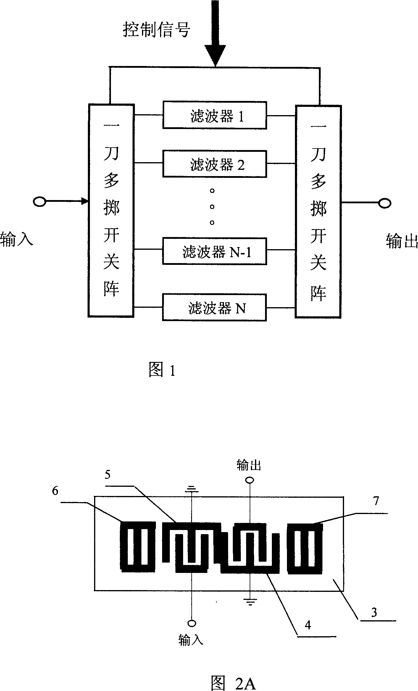
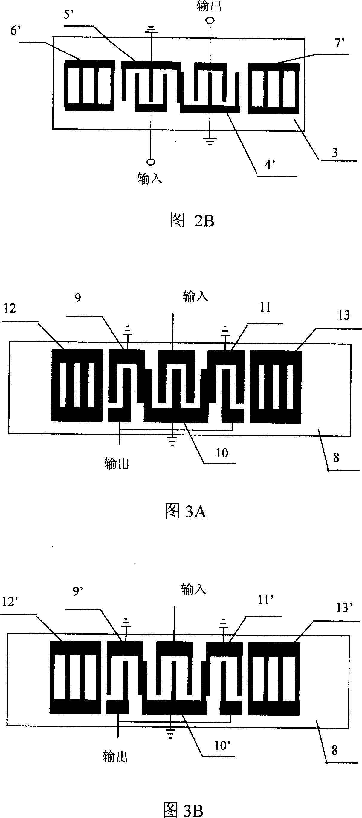
[0037] Fig. 1 is the functional block diagram of the wideband surface acoustic wave switchable filter group of the present invention, and it is made up of a plurality of surface acoustic wave filters 2 and one knife multi-throw switch 1, adds driving signal and can control two groups of switch arrays to switch simultaneously, makes in At a certain moment, only one of the channels is turned on, and the other channels are turned off, and all the power of the input signal is added to the channel to ensure that there is no loss of the combined network, where a single SAW filter chip adopts a longitudinally coupled resonant structure . Due to the wide span of the passband of the filter bank, in order to achieve the same bandwidth of each channel as possible, a 1-2 mode longitudinally coupled resonant structure (as shown in Figure 2A) or a 1-3 mode longitudinally coupled resonant structure is used on different substrate materials. Formula structure (as shown in Figure 3A). The deta...

Embodiment 2

[0046] On the basis of embodiment 1, when the channel increases to 16 channels (the center frequency of the last channel in the 16 channel filter banks of this embodiment is about 2 times of the center frequency of the first channel), 1-12 channels Adopt the same scheme as embodiment 1, channel 13-channel 16, adopt 64 ° Y-X LiNbO on the substrate 3 The 1-3 mode longitudinal coupling structure is fabricated on the above.

Embodiment 3

[0048] On the basis of embodiment 2, when the channel increases to 20 channels, 1-16 channels adopt the same scheme as embodiment 2, and channel 17-channel 20 adopts 64 ° Y-X LiNbO on the substrate 3 The 1-2 mode longitudinal coupling structure is made above, and it can be adjusted according to the actual situation in the specific operation.

[0049] When the number of required channels increases, by analogy with the above rules, each channel can have approximately the same bandwidth filter components.

[0050] The surface acoustic wave filter chip shown in Figure 2A is composed of a piezoelectric substrate 3 and two interdigital transducers 4,5 made on the piezoelectric substrate 3 and metal reflection grid arrays 6,7 at its two ends composition. The interdigital transducers 4 and 5 are not weighted, and the width and spacing of the interdigital electrodes are 0.25 wavelengths. The metal reflective grid arrays 6 and 7 use short-circuit grids, and the width and spacing of the...


PUM

PropertyMeasurementUnit
Insertion lossaaaaaaaaaa

Abstract

The invention is concerned with broadband low loss switch filter group of surface acoustic wave. The group relates to tow groups of multi-throw switch with one knife and some filters of surface acoustic wave. One group switch joins up the imports of some filters of surface acoustic wave, the other group joins up the fan-outs of some filters of surface acoustic wave and the tow groups of switch is corresponding to each other. The structure to said filter of surface acoustic wave is longitudinal coupling resonant to realize the low loss. Different channels adopt some different longitudinal coupling structure to get as same bandwidth as possible for each channel. The base plate is LiNbO3, LiTaO_3, and so on. This invention affords a kind of switch filter group of surface acoustic wave for broad band to communications system (single channel relative bandwidth is 2%-7.3%), low loss (containing the switch, less than 6.5dB) and higher stop-band limit (more than 40 dB ).

Description

technical field [0001] The invention relates to a surface acoustic wave switchable filter group used in communication, in particular to a wideband low-loss surface acoustic wave switchable filter group. Background technique [0002] The surface acoustic wave filter bank is composed of multiple surface acoustic wave filters plus matching networks and switching circuits, and has one input and multiple output components. The output signal is divided by frequency, which can be used for frequency sorting and synthesis. It is mainly used in frequency synthesis, frequency hopping communication and other systems. The present invention relates to a surface acoustic wave filter bank applied to a frequency hopping communication system. [0003] A big disadvantage of the prior art is that the filter insertion loss is large, thus limiting the bandwidth and the number of channels of the filter bank. This is a result of the traditional bi-directional transducer design used in the prior ...

Claims


Application Information

Patent Timeline
IPC IPC(8): H03H19/00H03H11/00H03H9/64
Inventor 何世堂刘久玲李顺洲
Owner INST OF ACOUSTICS CHINESE ACAD OF SCI
Why Eureka
Try Eureka