Method for preparing in-situ growing carbon nano tube chemical decoration electrode
A carbon nanotube, in-situ growth technology, applied in the direction of electrochemical variables of materials, etc., can solve the problems of adverse effects on the electrochemical performance of carbon nanotube chemically modified electrodes, insufficient contact interface bonding, large contact resistance, etc., and achieve electron transfer. The effect of fast speed, small contact resistance and large response current
- Summary
- Abstract
- Description
- Claims
- Application Information
AI Technical Summary
Problems solved by technology
Method used
Image
Examples
Embodiment 1
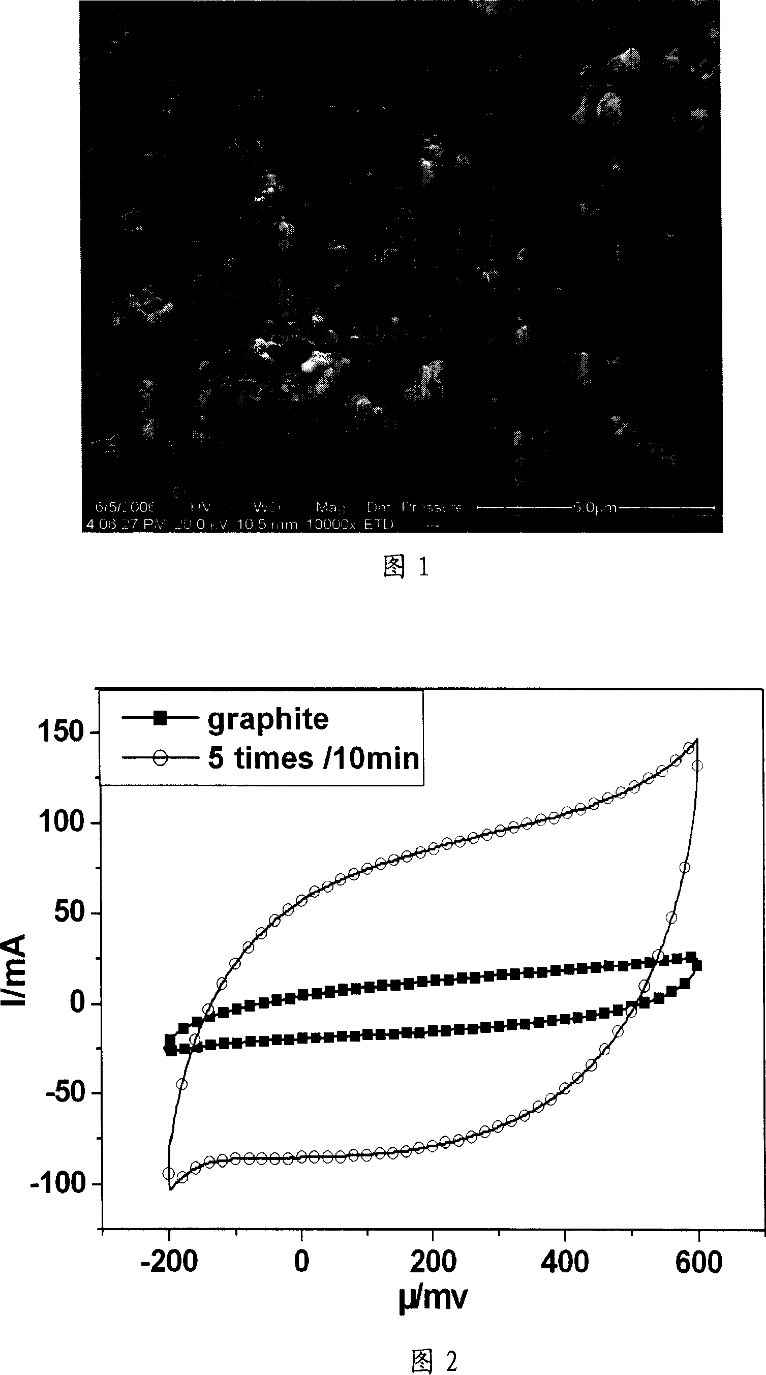
[0023] a) Prepare and attach catalyst particles on solid electrode graphite by impregnation method: first, citric acid (C 6 h 8 o 7 ·H 2 O) was added to 20% Ni(NO 3 ) 2 solution, C 6 h 8 o 7 ·H 2 O (analytically pure) and Ni (NO 3 ) 2 ·6H 2 The molar ratio of O (analytically pure) is 2: 1 to make impregnating liquid; Then the graphite sheet (1cm * 8cm) as solid electrode is put into above-mentioned impregnating liquid and dipped for 20 minutes, then kept at 150 ℃ for 5 minutes; impregnated Repeat the heat preservation operation 5 times, after the last heat preservation, perform ultrasonic cleaning, and then heat preservation at 200°C for 1 hour. That is, a graphite electrode with a particle diameter of 1-100 nm particle metal nickel catalyst adhered on the surface is obtained.
[0024] b) In-situ growth of carbon nanotubes on solid electrodes by chemical vapor catalytic cracking: put the above graphite electrodes attached with nickel catalysts into a horizontal tub...
Embodiment 2
[0027] The method of this example is basically the same as the production method of Example 1, the difference is only: do not add citric acid, but use Co(NO 3 ) 2 and Ni(NO 3 ) 2 The mixed solution of Co(NO 3 ) 2 and Ni(NO 3 ) 2 The molar ratio is 1:1. The graphite electrode is impregnated to obtain the graphite electrode with particle diameters of 1-100nm particle metal nickel and cobalt catalyst attached to the surface. The carbon source for growing carbon nanotubes is CH 4 The shielding gas is argon.
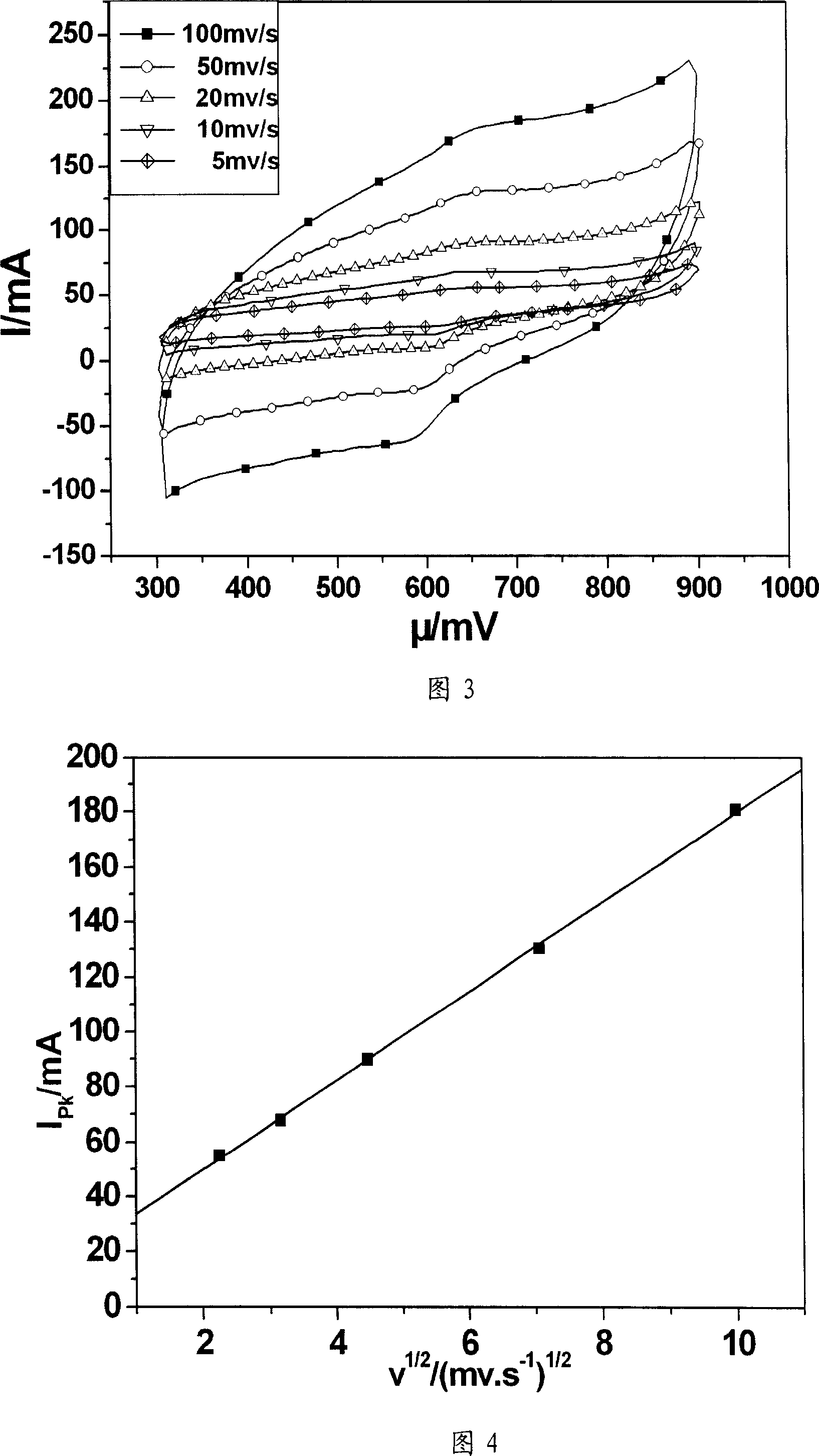
[0028] Fig. 3 is the in situ growth carbon nanotube chemically modified graphite electrode prepared by the method of this example at 0.01M[Fe(CN)] 4- +0.01M[Fe(CN)] 3- Cyclic voltammetry curves at different voltage scanning speeds (in mv / s) in the mixed solution of +0.5M KCl. Figure 4 is at 0.01M[Fe(CN)] 4- +0.01M[Fe(CN) 3- The relationship between the oxidation current and the square root of the voltage scanning speed in the mixed solution of +0.5M KCl. It can ...
Embodiment 3
[0030] The method of this example is basically the same as the production method of Example 1, the difference is only: do not add citric acid, but use Co(NO 3 ) 2 , Fe(NO 3 ) 3 and Ni(NO 3 ) 2 The mixed solution of Co(NO 3 )2 , Fe(NO 3 ) 3 and Ni(NO 3 ) 2 The molar ratio is equal to 1:1:1. The graphite electrode is impregnated to obtain the graphite electrode with particle diameters of 1-100nm particle metal nickel, cobalt and iron catalyst attached to the surface. The carbon source for growing carbon nanotubes was n-hexane (C 6 h 14 ).
PUM
| Property | Measurement | Unit |
|---|---|---|
| Particle size | aaaaa | aaaaa |
Abstract
Description
Claims
Application Information
 - R&D
- Intellectual Property
- Life Sciences
- Materials
- Tech Scout
- Unparalleled Data Quality
- Higher Quality Content
- 60% Fewer Hallucinations
Browse by: Latest US Patents, China's latest patents, Technical Efficacy Thesaurus, Application Domain, Technology Topic, Popular Technical Reports.
© 2025 PatSnap. All rights reserved.Legal|Privacy policy|Modern Slavery Act Transparency Statement|Sitemap|About US| Contact US: help@patsnap.com


