
Oscillatory auger hole and dredging device

A technology of vibrating screw and auger rod, which is applied to mechanically driven excavators/dredgers, drill bits, drilling equipment, etc., can solve problems such as hole wall collapse, reduce friction resistance, reduce vibration mass and amplitude Effect

Inactive Publication Date: 2007-07-11
孙孝庆
View PDF0 Cites 24 Cited by
  • Summary
  • Abstract
  • Description
  • Claims
  • Application Information

AI Technical Summary

Problems solved by technology

[0012] For the problems existing in the prior art, the primary purpose of the present invention is to provide a device that can overcome the problems existing in the existing long auger drilling machine, that is: reduce the frictional resistance between the silt and the helical surface, and use the same diameter auger The rod can be expanded to drill holes with different diameters, which solves the problem of hole wall collapse when drilling in loose strata; the main purpose of the invention is to introduce the effective non-circulating liquid engineering method in geotechnical engineering into dredging operations, greatly Significantly reduce secondary pollution of water, improve construction efficiency, reduce energy consumption, and reduce costs

Method used


Image

  • Oscillatory auger hole and dredging device
  • Oscillatory auger hole and dredging device
  • Oscillatory auger hole and dredging device

Examples


Embodiment Construction

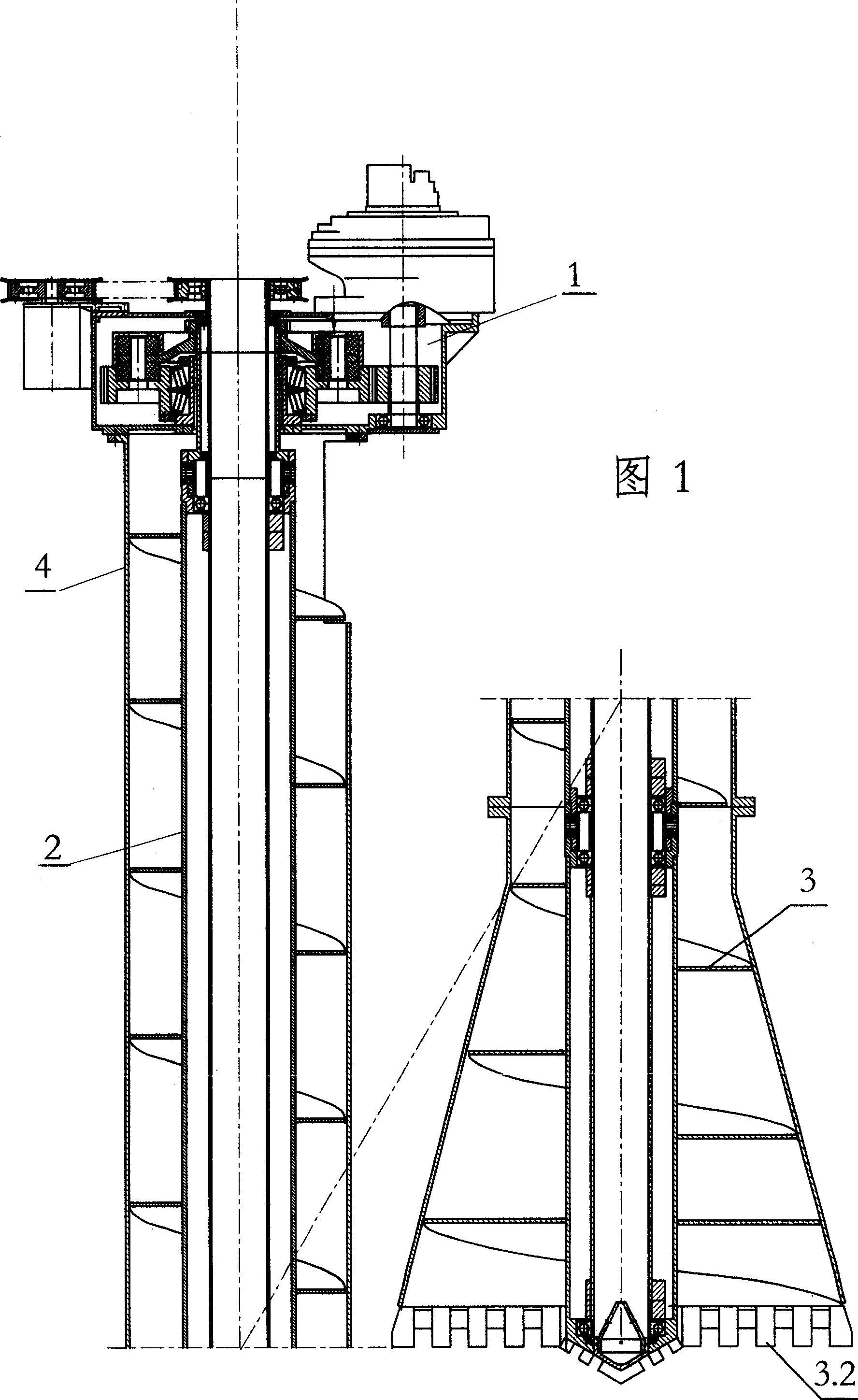
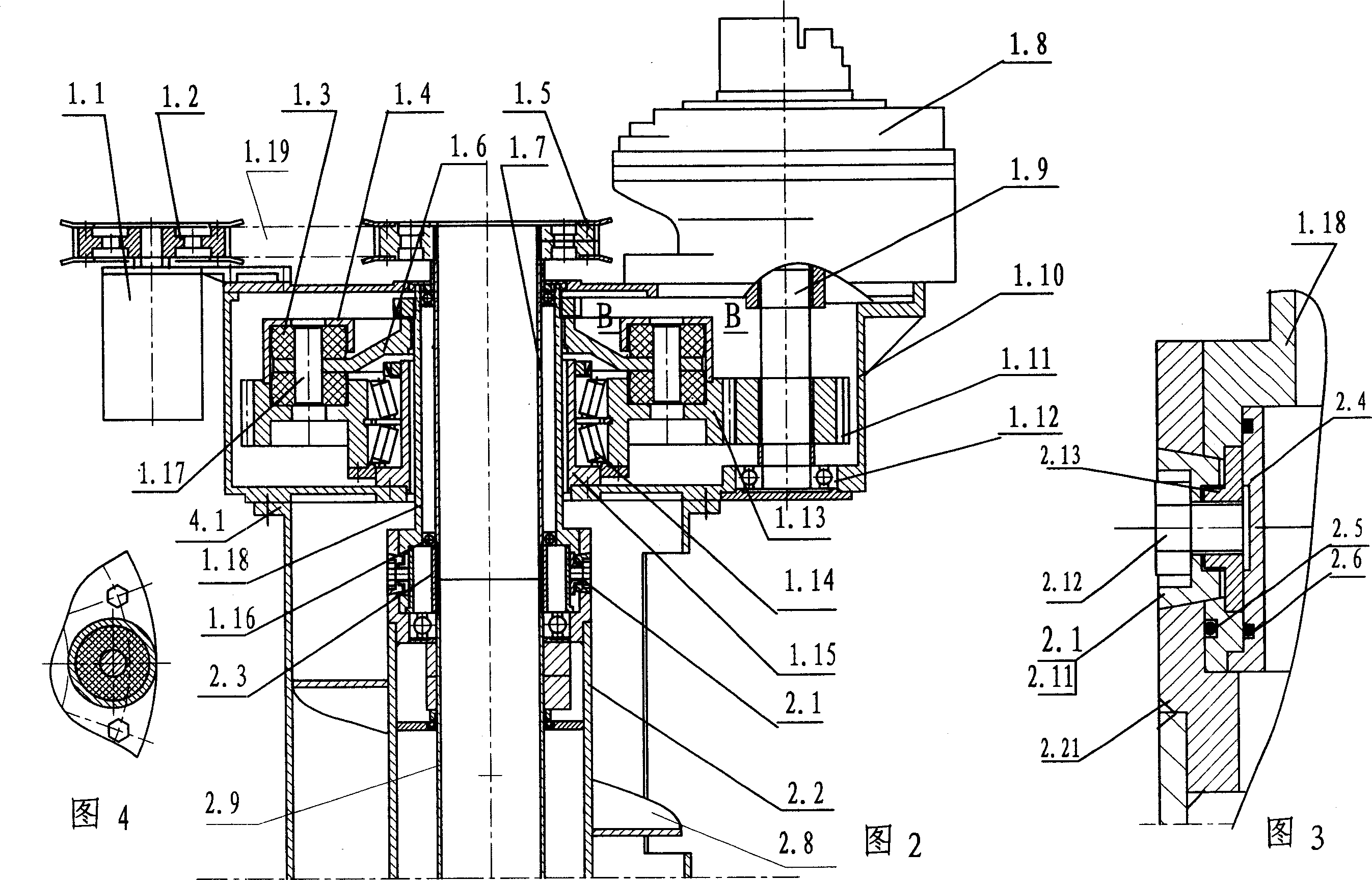
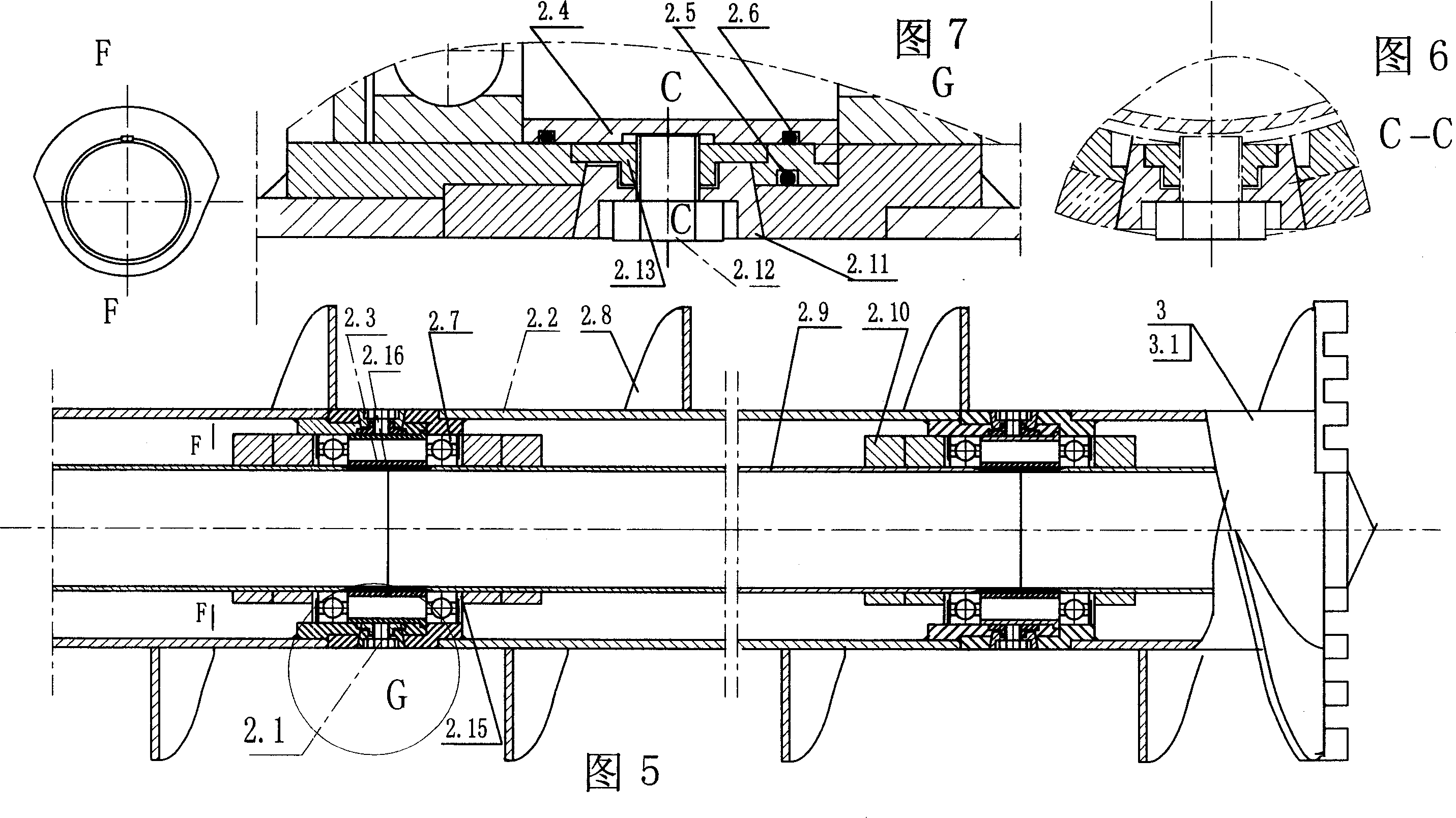
[0050] As shown in Fig. 1, Fig. 2, Fig. 3 and Fig. 4, the vibrating helical drilling and dredging device of the present invention is composed of a power head 1, an auger rod 2, a central conduit 2.9, a drill bit 3 and a casing 4; the power head 1 Located on the top of the auger rod 2, a low-speed hydraulic motor 1.8 is located on the upper part of the power head case 1.10, the output shaft of the low-speed hydraulic motor extends downward into the case, the axis is parallel to the center line of the auger rod 2, and offset by a distance, the low-speed The hydraulic motor 1.8 is connected with the pinion 1.11 through the spline shaft 1.9, the upper end of the spline shaft 1.9 is connected with the output shaft of the low-speed hydraulic motor, the lower end is installed in the power head chassis 1.10 with the ball bearing 1.12, the pinion 1.11 meshes with the large gear 1.13, and the large The gear 1.13 is installed on the chassis mandrel 1.15 with a pair of conical thrust beari...


PUM


Abstract

The invention relates to a vibration helical drilling hole and dredging device for drilling hole of stratum and dredging, comprising power head, helical drilling bar, central guide tube, drill bit, expanding drill bit, casing pipe and expanding casing pipe so on. In working, the drilling bar and drill bit generate high-frequency micro-breadth vibration and liquefaction is generated between soil and helical face so that friction resistance is decreased and plugging in often is avoided. The helical drilling bar with the same diameter can be used to drill holes with different diameters by expanding diameter. The central guide tube is used to jet concrete while drilling, it is more important to carry dredging operation by no cycling liquid method. The vibration spiral is used to transport bottom mud and the water is not used as the medium for transporting the bottom mud. So secondary pollution for water is decreased greatly, the efficiency is improved and the energy consumption is decreased. It is provided with easy production, low cost for equipment and construction.

Description

technical field [0001] The invention relates to a "vibrating auger drilling and dredging device" which can be used not only for stratum drilling but also for dredging Background technique [0002] The existing long helical drilling machine uses screw conveying to transport the sediment out of the hole bottom, instead of using water as the circulating medium and pumps out the mud-water mixture, so it is called non-circulating fluid transportation, because the non-circulating fluid transportation meets the requirements of environmental protection , has been widely used, the existing problems are: [0003] (1) The frictional resistance between the sand and the spiral surface is very large, which not only consumes a lot of energy, but when the viscosity of the sand increases, it will often stick to the screw blades and cause blockage. The conveying stops and the drilling cannot be continued. It is very laborious and time-consuming to remove the soil that blocks the screw plug b...

Claims


Application Information

Patent Timeline
IPC IPC(8): E21B10/44E02F3/06
Inventor 孙孝庆
Owner 孙孝庆
Learn More