Submarine low loss cable system and method for arranging a submarine cable landfall system

a low-loss, submarine-type technology, applied in the field of submarine-type low-loss cable systems and methods for arranging submarine-type cable landfall systems, can solve the problems of increasing cable system temperature, increasing the cross-sectional area of the conductor, and increasing the temperature of the cable system, so as to reduce the cross-sectional area of the submarine cable, increase the conductor cross-sectional area, and facilitate the effect of pulling in

Active Publication Date: 2018-08-21
NEXANS
View PDF21 Cites 1 Cited by
  • Summary
  • Abstract
  • Description
  • Claims
  • Application Information

AI Technical Summary

Benefits of technology

[0011]The arrangement according to the invention reduces the need for a highly increased conductor cross sectional area in said section of the cable at a landfall region. Besides the economic and production related benefits, decreasing the cross sectional area of a submarine cable would make pull-in operations easier, and would give considerable savings related to handling equipment such as rollers, storage drums etc. The dimensions of the HDD pipe can also be reduced.
[0023]Electrically connecting the second layers of each core provides a cross-over flow of circulating currents between the second layers, thereby ensuring that the potential at the connection point is zero. At the connection point the second layers of the cable's first section will also be at zero potential, and since the second layers of the cable's first section are terminated in an open ended termination there will not be any circulating currents in the second layers of the cable's first section. With no circulating currents in the first section, which coincides with the area of unfavourable environmental conditions such as the landfall region, losses and heat generation in the second layer will be reduced. Thus, the cable will retain its ampacity without the need for a highly increased cross sectional area along the first section.

Problems solved by technology

This circulating current results in power loss and generation of heat in the metallic sheath, causing the temperature of the cable system to increase.
An increase of temperature can lead the cable insulation to deteriorate.
The electrical current is a fixed requirement, specified by how much power the cable needs to deliver, and it is usually not an option to reduce this parameter.
High voltage cable systems are often required to traverse stretches of water, resulting in relatively large variations in the heat dissipating properties of the cable's surroundings.
When the cable is brought ashore, it may either pass an underground region where the soil is not saturated with water, it may be brought along a surface of the ground, it may be provided elevated on a frame in the air or it may pass through a submarine region with inferior heat dissipating properties.
In all these cases, the landfall region will usually have reduced heat dissipating properties, resulting in a so-called thermal bottleneck.
Increasing the cross sectional area of the conductor has many negative effects: it requires substantially more material, such as copper, leading to an increase in production costs.
Often the increase of the cross sectional area is so large that production is not practically possible.
An increased cross sectional area of the conductor also leads to significantly higher sheath losses.
Handling a submarine cable with a large cross sectional area also presents a multitude of problems due to added weight and size of the cable, requiring corresponding dimensioning of systems on board a cable-laying vessel.
However, this still leaves a substantial section of the cable system with a conductor of an undesirably large cross sectional area.

Method used


Image

  • Submarine low loss cable system and method for arranging a submarine cable landfall system
  • Submarine low loss cable system and method for arranging a submarine cable landfall system
  • Submarine low loss cable system and method for arranging a submarine cable landfall system

Examples


Embodiment Construction

[0049]The inventive concept will now be described more fully hereinafter with reference to the accompanying drawings.

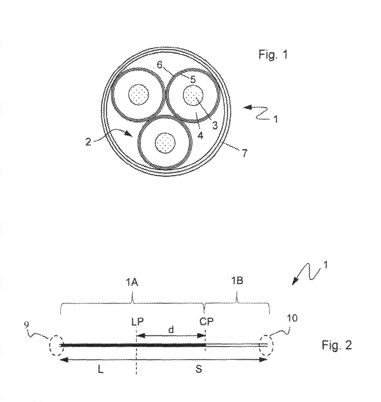
[0050]FIG. 1 schematically illustrates an example of a cross section a cable 1, where the cable is shown with three cable cores 2. However, this invention is not limited to a three-core cable, and the cable may comprise two or any higher number of cores, as is deemed suitable for the cables necessary purposes.

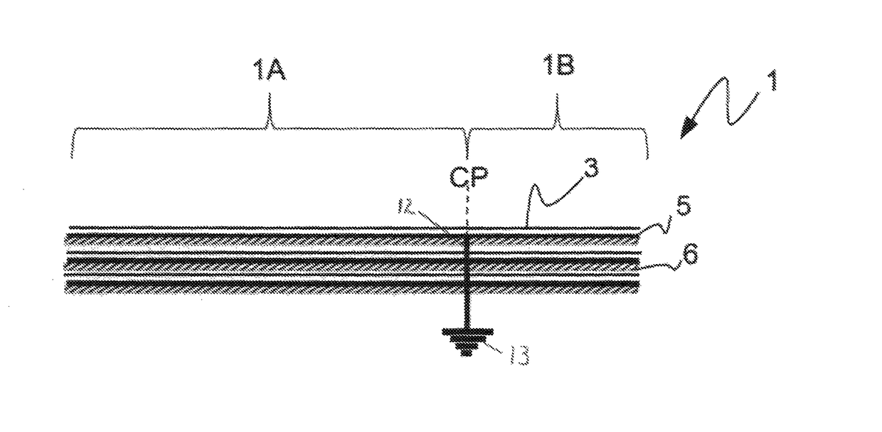
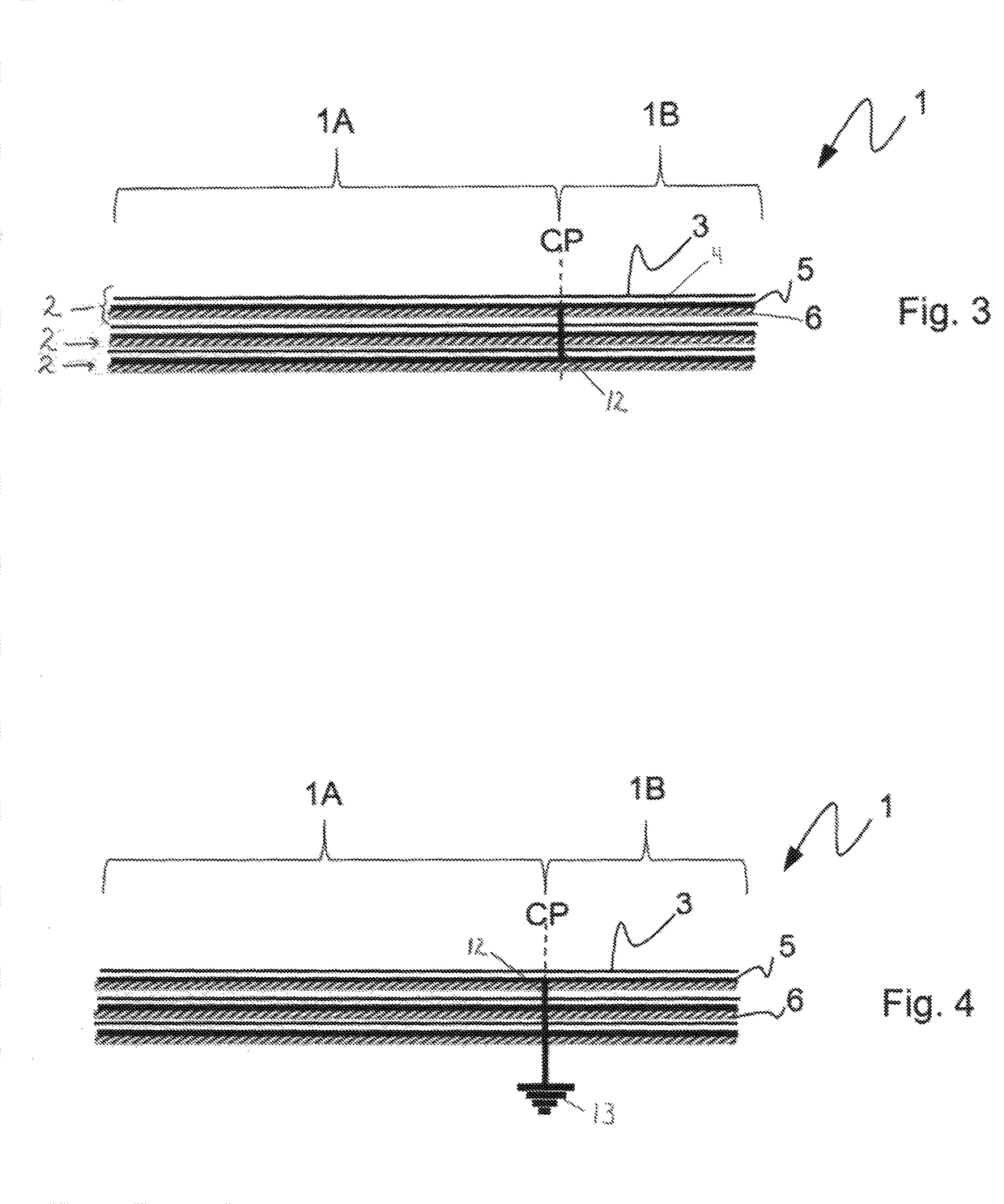
[0051]Each core 2 comprises an electrical conductor 3 arranged in the centre of the core 2, the electrical conductor 3 has a cross sectional area, which affects the ampacity of the cable. As will be explained in further detail, the cable may have different sized cross sectional areas along the first and second sections. The conductor 3 may comprise copper or aluminium, or alloys of these as will be known to the person skilled in the art.

[0052]Arranged radially outside each conductor 3 is a first, electrically insulating layer 4. The electrically insulating layer ...


PUM

PropertyMeasurementUnit
distanceaaaaaaaaaa
distanceaaaaaaaaaa
distanceaaaaaaaaaa

Abstract

A low loss cable system adapted for use as a cable landfall system. The cable system comprises a cable having a plurality of cores. Each core comprises a conductor, a first insulating layer, a second electrically conductive layer and a third layer. The cable comprises two sections, connected at a connection point CP. A first section of the cable is arranged to be exposed to a landfall area and a second section of the cable is arranged to be exposed to a submarine area. The cable is arranged such that circulating currents are prevented or reduced in the second conductive layers of the cable in the section exposed to the landfall area, thus assisting in maintaining the ampacity of the cable in this section without, or by reducing, the need to increase the cross sectional area of the cable in the landfall area. This is accomplished by electrically connecting the second conductive layers of the cores to each other at the connection point. At a distal end of the first section of the cable, the second layers are arranged to leave an open ended termination, thus avoiding a closed circuit that would otherwise create circulating currents in the second layers of the first section, thus maintaining ampacity.

Description

TECHNICAL FIELD[0001]The present invention relates to cable systems, in particular the invention relates to an arrangement for maintaining ampacity in a section of a high voltage alternating current submarine cable traversing a landfall region.BACKGROUND ART[0002]High voltage alternating current (HVAC) cable systems comprise a conductor located at the centre of the cable, for delivering an electric current. The conductor is usually surrounded by plurality of layers arranged radially outside of the conductor, where each layer has a specific function. A first layer arranged over the conductor may comprise cross-linked polyethylene (XLPE), providing electrical insulation.[0003]Arranged radially outside of the XLPE layer there may be provided a metallic sheath, for electrically shielding and protecting the conductor from abrasion, corrosion and moisture. The current flowing through the conductor induces a voltage in the metallic sheath surrounding the conductor, and if the sheath forms ...

Claims


Application Information

Patent Timeline
Patent Type & Authority Patents(United States)
IPC IPC(8): H01B7/00H01B7/14H02G1/06H02G9/02H01B7/02
CPCH01B7/009H01B7/0225H02G9/02H02G1/06H01B7/14H02G1/10H01B7/26H01B9/029
Inventor HATLO, MARIUSOLSEN, ESPEN
Owner NEXANS
Why Eureka
Try Eureka