Apparatus and method for the precision application of cosmetics

a cosmetic and precision technology, applied in the field of cosmetics, can solve the problems of not being practical for traditional cosmetic deposition, not being able to adapt digital technologies, and each prior art technique has limitations, so as to improve appearance, slow movement, and cover the face or other area more quickly

Active Publication Date: 2018-10-09
TCMS TRANSPARENT BEAUTY LLC
View PDF197 Cites 23 Cited by
  • Summary
  • Abstract
  • Description
  • Claims
  • Application Information

AI Technical Summary

Benefits of technology

[0018]It is another aspect of the present invention to provide a digital eraser brush that the user may move back and forth, like a common eraser, over an area of skin or other human feature to scan that area and quickly deposit one or more RMAs in response to the skin attributes identified there.
[0033]One principle of the Eraser Brush is that skin reflectance may be measured accurately by employing multiple inexpensive sensors and light sources. This plurality of light sources and sensors provide a rich source of information which can be used to provide an accurate calibration of the device to compensate for distance from target and angle of measurement. A polarizing filter may be used to eliminate the effects of gloss.

Problems solved by technology

There has been little motivation to adapt digital technologies to cosmetic deposition because there has been no compelling reason to substitute digital technologies for the “fingers and sticks” which have been used to apply cosmetic agents for many centuries.
In addition to the more natural appearance, sparse applications have a much lighter feel than traditional cosmetics; and the sparse applications permit the use of compositions and formulations, such as for improved durability, that may not be practical for traditional cosmetic deposition.
Each of these prior art techniques has limitations.
These application methods make prior art cosmetics imprecise, labor intensive, expensive, and sometimes harmful, when compared to the techniques of the present invention.
Manual cosmetic applications are imprecise compared to computer-controlled techniques, and this imprecision may make them less effective.
For example, the heavy application of a foundation base for makeup may cause an unattractive, caked-on appearance.

Method used


Image

  • Apparatus and method for the precision application of cosmetics
  • Apparatus and method for the precision application of cosmetics
  • Apparatus and method for the precision application of cosmetics

Examples


example

[0154]In this example, three pairs 158, 160, and 162, of LEDs and sensors are arranged on a sensor ring 150. Each LED in sensor is aimed at a center point at a first distance from the ring.

[0155]In FIG. 21A, the plane of intersection is closer than the aim distance. Although the beam profiles 164, 166, and 168 are shown as circular patterns in this example, the actual beam profiles would be elliptical.

[0156]In FIG. 21B, the plane is near the aim distance, and the beam profiles 164, 166, and 168 are closer to the center than in FIG. 21A.

[0157]In FIG. 21C, the plane is farther than the aim distance, and the beam profiles have crossed the center point. As the distance increases, these beam profiles will get further from the center.

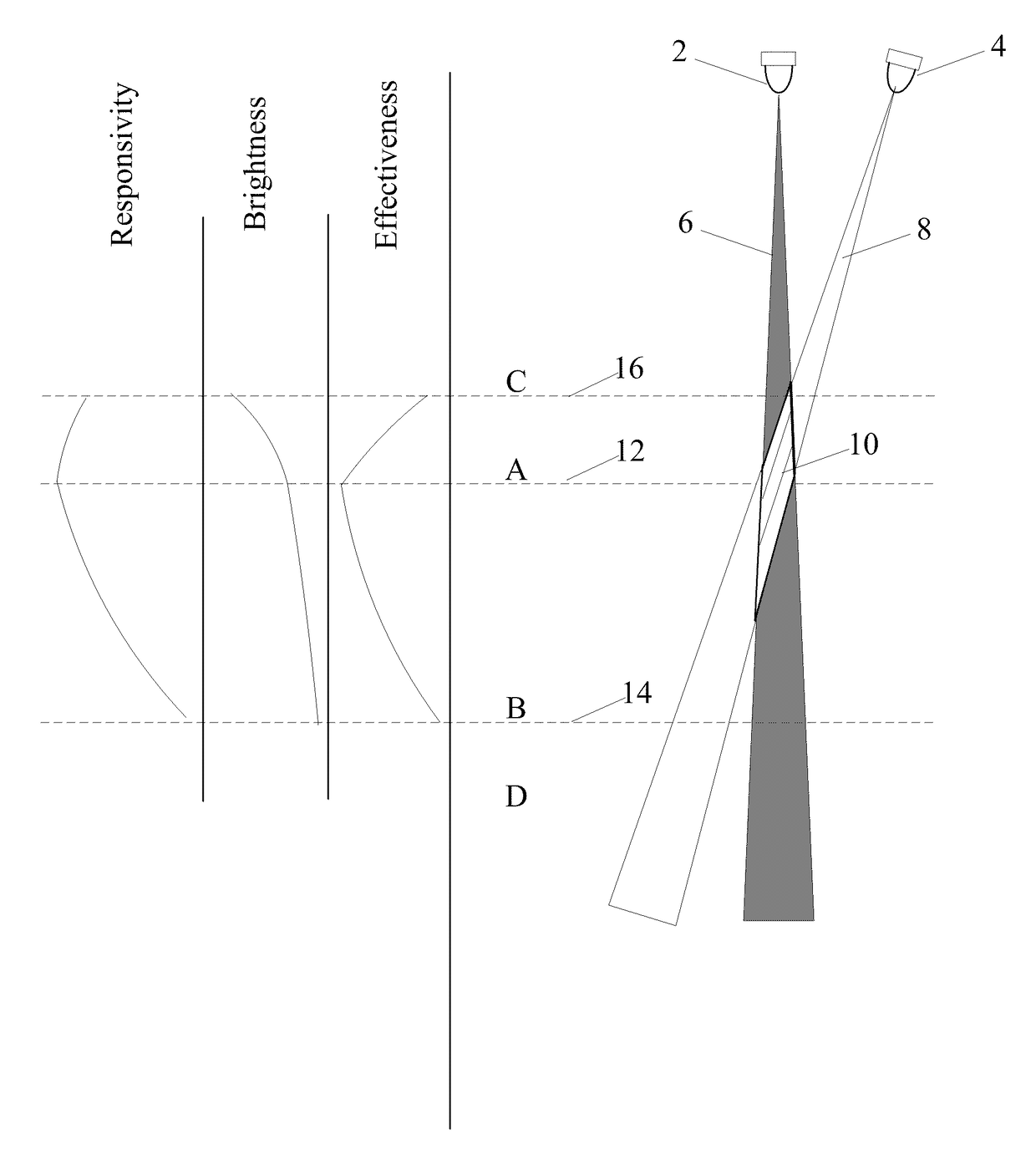
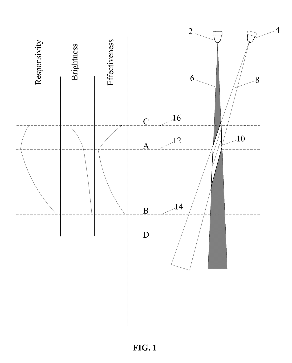
Region of Invariant Net Gain

[0158]Referring now to FIG. 1, the light source 2 may be focused into a beam 6, and the sensor 4 may also be considered as being focused into a beam 8. It may be understood that the region of effectiveness 10 is the intersection of...

example configuration

[0185]In this example, six pairs of LEDs and sensors are equally spaced around the example ring. The three pair of sensors are aimed at a first height of ⅜ inch, and an alternating three pair of sensors are aimed at a second height of 9 / 8 inch.

[0186]In one embodiment, it is desirable to cycle the sequence of lighting of the six LEDs so that each LED is on at a time when all other LEDs are off. As each of the first set of LEDs (L1, L2, and L3) is turned on, data from each of the first set of sensors (S1, S2, and S3) is acquired for each of the first set of LEDs in both an “ON” and “OFF” state. Then, as each of the second set of LEDs (L4, L5, and L6) is turned on, data from each of the second set of sensors (S4, S5, and S6) is acquired for each of the second set of LEDs. This sequencing can be accomplished by a timing circuit as discussed below, or by having each LED driven by a modulation function.

[0187]In this case, the device sequencing is based on 88 kHz so that standard audio equ...

example simulation

[0207]In one example simulation, LED factors include Intensity (I), Wavelength, Beam angle (Θ), radial distance from centerline (rL), the angular location from a reference axis (βL), and angle of aim (γL). The sensor factors include the photodiode sensitivity at the wavelength of the LED, the viewing angle (Θ), radial distance from centerline (rS), the angular location from a reference axis (βS), and angle of aim (γS). The local surface is described as a plane of interest located a distance (h) below the center of the ring, and having a first axis tilt (αx) and a second axis tilt (αy).

[0208]In this example, the plane of interest comprises a plurality of cells. Each LED projects a beam to the plane of interest, and that beam profile can be calculated at each cell center as the product of a Gaussian distribution component and a 1 / L2 component to account for the decrease in illumination per surface area as the distance L increases.

[0209]FIG. 39 shows a two-dimensional example of this t...


PUM


Abstract

One or more reflectance modifying agent (RMA) such as a pigmented cosmetic agent is applied selectively and precisely with a controlled spray to human skin according to local skin reflectance or texture attributes. One embodiment uses digital control based on the analysis of camera images. Another embodiment, utilizes a calibrated scanning device comprising a plurality of LEDs and photo diode sensors to correct reflectance readings to compensate for device distance and orientation relative to the skin. Ranges of desired RMA application parameters of high luminance RMA, selectively applied to middle spatial frequency features, at low opacity or application density are each significantly different from conventional cosmetic practice. The ranges are complementary and the use of all three techniques in combination provides a surprisingly effective result which preserves natural beauty while applying a minimum amount of cosmetic agent.

Description

CROSS-REFERENCE TO RELATED APPLICATIONS[0001]This patent application is related to U.S. Provisional Patent Application No. 60 / 940,548 filed May 29, 2007 for “Apparatus and method for the precision application of cosmetics” and claims the filing date of that Provisional application.[0002]This patent application is related toU.S. Provisional Patent Application No. 60 / 944,526 filed Jun. 18, 2007;U.S. Provisional Patent Application No. 60 / 944,527 filed Jun. 18, 2007;U.S. Provisional Patent Application No. 60 / 944,528 filed Jun. 18, 2007;U.S. Provisional Patent Application No. 60 / 944,529 filed Jun. 18, 2007;U.S. Provisional Patent Application No. 60 / 944,531 filed Jun. 18, 2007; andU.S. Provisional Patent Application No. 60 / 944,532 filed Jun. 18, 2007.[0003]This patent application incorporates by reference the specification, drawings, and claims of U.S. patent application Ser. No. 11 / 503,806 filed Aug. 14, 2006 for “SYSTEM AND METHOD FOR APPLYING A REFLECTANCE MODIFYING AGENT TO IMPROVE TH...

Claims


Application Information

Patent Timeline
Patent Type & Authority Patents(United States)
IPC IPC(8): A45D44/00B41J3/36B41J3/407B41J3/44B05B5/16A45D33/02
CPCA45D44/005B05B5/1691B41J3/36B41J3/44B41J3/4073A45D2200/057A45D33/02A45D2044/007
Inventor EDGAR, ALBERT D.RABE, THOMAS E.IGLEHART, DAVID C.YEAGER, RICK B.
Owner TCMS TRANSPARENT BEAUTY LLC
Why Eureka
Try Eureka