
Sintered alloy and production method therefor

a technology of sinter alloy and production method, which is applied in the direction of turbines, mechanical equipment, etc., can solve the problems of insufficient cr in stainless steel, corrosion may occur in a heat-resistant bearing for a turbocharger, and progressive corrosion, etc., to achieve high corrosion resistance, corrosion resistance, and corrosion resistance. , the effect of not easily corroded

Inactive Publication Date: 2018-10-09
RESONAC CORPORATION
View PDF3 Cites 0 Cited by
  • Summary
  • Abstract
  • Description
  • Claims
  • Application Information

AI Technical Summary

Benefits of technology

The present invention provides a sintered alloy with high heat resistance, wear resistance, and corrosion resistance against salt damage that may occur in cold-weather regions. The alloy has a metallic structure with a matrix of steel containing a high concentration of Cr and carbides dispersed in the matrix. The carbides are formed so as to cover a boundary of the matrix and the carbides, called "chromium-depleted area," which can become a starting point of progression of corrosion. The alloy is produced by a specific production method. This alloy is suitable for use in turbocomponents of turbochargers and exhibits superior performance under high temperatures and is not easily corrodes.

Problems solved by technology

The chloride ions contained in the water in large amounts break a passive film that formed on the surface of stainless steel, causing progressive corrosion.
Accordingly, corrosion may occur in a heat resistant bearing for a turbocharger due to salt damage.
Then, as the passive film melts, Cr is correspondingly supplied from an inside of the stainless steel, whereby the amount of Cr in the stainless steel becomes insufficient.
Such corrosion may progress even in a sintered alloy as disclosed in Japanese Patent No. 3784003 under corrosive conditions that may cause salt damage.

Method used


Image

  • Sintered alloy and production method therefor
  • Sintered alloy and production method therefor

Examples


examples

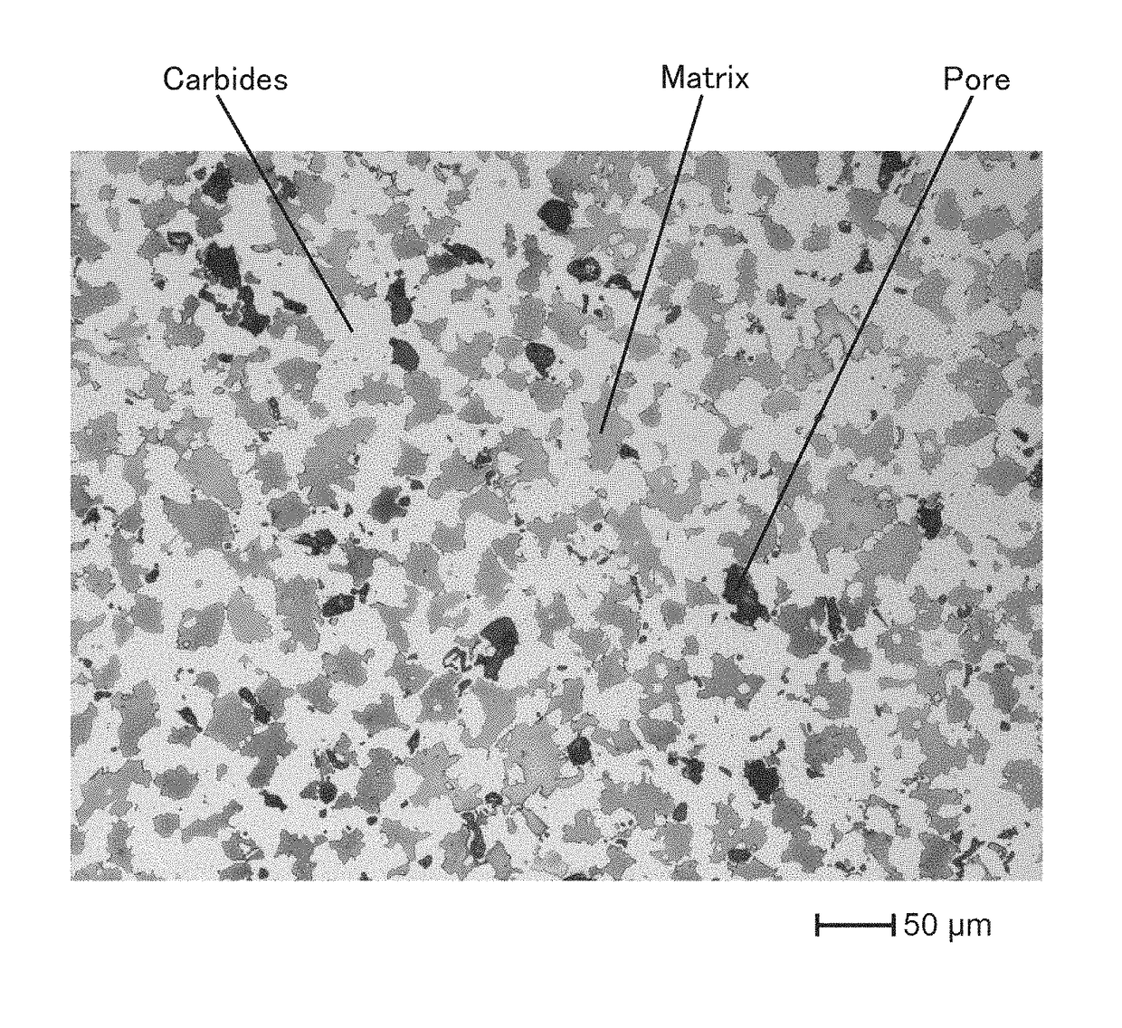
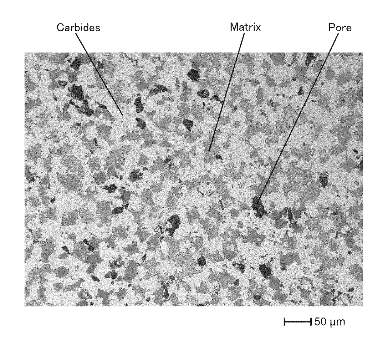
[0031]First, iron alloy powders and iron-phosphorous alloy powders having a composition shown in Table 1, and a graphite powder, were prepared, and the iron-phosphorous alloy powder and the graphite powder were added to the iron alloy powder and were mixed at the mixing ratio shown in Table 1, whereby mixed powders were obtained. The mixed powders were compacted into columnar shaped green compacts, which had a compact density of 5.5 Mg / m3 and had an outer diameter of 10 mm and a height of 10 mm, or disk shaped green compacts, which had a compact density of 5.5 Mg / m3 and had an outer diameter of 24 mm and a height of 8 mm. Then, these green compacts were sintered at 1250° C. in a vacuum atmosphere of 100 Pa, whereby sintered alloy samples Nos. 01 to 28 were formed. The overall compositions of these sintered alloy samples are also shown in Table 1.

[0032]The columnar shaped sintered alloy samples were used to measure a sintered compact density by the sintered density measuring method s...


PUM

PropertyMeasurementUnit
mass %aaaaaaaaaa
mass %aaaaaaaaaa
heightaaaaaaaaaa

Abstract

A sintered alloy having superior heat resistance and superior wear resistance and also having corrosion resistance against salt damage that may occur in cold-weather regions, and a production method therefor, are provided. The sintered alloy consists of, by mass %, 32.4 to 48.4% of Cr, 2.9 to 10.0% of Mo, 0.9 to 2.9% of Si, 0.3 to 1.8% of P, 0.7 to 3.9% of C, and the balance of Fe and inevitable impurities, and it has a density ratio of not less than 90% and includes carbides that are dispersed in a matrix of a metallic structure thereof.

Description

BACKGROUND OF THE INVENTION[0001]Technical Field[0002]The present invention relates to a sintered alloy and relates to a production method therefor. The sintered alloy may be suitably used for, for example, turbo components of turbochargers, and specifically, heat-resistant bearings that must have heat resistance, corrosion resistance, and wear resistance, and the like.[0003]Background Art[0004]In general, in a turbocharger fixed to an internal combustion engine, a turbine is rotatably supported by a turbine housing that is connected to an exhaust manifold of the internal combustion engine. Exhaust gas flowing in the turbine housing flows from the outer circumference of the turbine into the turbine and is discharged in the axial direction, thereby rotating the turbine. Then, a compressor, which is provided at the same shaft as the shaft of the turbine and is at a side opposite to the turbine, is rotated, whereby air to be supplied to the internal combustion engine is compressed. In ...

Claims


Application Information

Patent Timeline
Patent Type & Authority Patents(United States)
IPC IPC(8): C22C38/18C22C38/36C22C38/02C22C30/00C22C38/34C22C38/22C22C1/05C22C33/02C22C1/10C22C1/08B22F5/00
CPCC22C38/36B22F5/009C22C38/34C22C38/22C22C1/05C22C1/08C22C1/10C22C30/00C22C33/0207C22C33/0285C22C38/02B22F2998/10B22F1/0003B22F3/02B22F3/10B22F1/09B22F1/12
Inventor FUKAE, DAISUKEKAWATA, HIDEAKI
Owner RESONAC CORPORATION
Learn More