Triple software redundancy fault tolerant framework architecture

a software redundancy and framework architecture technology, applied in the field of digital data processing, can solve the problems of reducing the performance of commercial high-performance technologies, reducing consuming commercial high-performance technologies, so as to reduce the size and weight of satellites, optimize the “size, weight and power” trade-off, and improve the performance/power consumption ratio. effect of hardware on-board size and weigh

Active Publication Date: 2018-10-09
THALES SA
View PDF11 Cites 0 Cited by
  • Summary
  • Abstract
  • Description
  • Claims
  • Application Information

AI Technical Summary

Benefits of technology

[0010]Cheaper and faster commercial processors (off-the-shelf—COTS) can be used. For example, satellite on-board payload applications can use modern processors, instead of traditional “rad-hard” digital integrated circuits. In particular, multi-core processors can be used (such processors are not manufactured for such radiation conditions existing in Space domain). Some embodiments thus enable high-bandwidth data processing and algorithm intensive computation. The tolerance of these multi-core processors to radiation-induced faults in Space domain is improved.
[0012]On-board satellites engineering is reduced, as well as purchase or acquisition costs while preserving application payload fault tolerance effectiveness to radiation-induced faults.
[0013]Embodiments of the invention in general provide flexible, scalable and reusable systems in Space domain critical missions. The described mixed SW / HW architecture is mission independent, i.e. generic and therefore reusable. The “Size, Weight and Power” (SWaP) trade-off is optimized. The performance / power consumption ratio and reduction of hardware on-board size and weight is improved. Computing boards can comprise less (and better) chips which participates to reduce satellites size and weight.
[0018]In one embodiment, the hypervisor can be a type I (1, one) hypervisor. This type of hypervisor generally corresponds to a software program running directly on top of the hardware layer, and is usually called “bare metal” hypervisor. It is generally a thin source code layer with a small memory footprint and runtime overhead. The advantage of this embodiment is that the small amount of code involved can render the overall solution less prone to errors. In another embodiment, the hypervisor can be a type II (2, two) hypervisor. This type of hypervisor corresponds to a software program relying on an Operating System (OS), and is usually called Type II hypervisor. Such hypervisors generally provide richer features, are generally less hardware specific but they also generally lead to longer execution time. The amount of software code involved is usually more important (but for example lightweight operating system distributions supporting virtualization are available and can blur the difference). In view of objective and foreseeable evolutions of the architecture of hardware processors, a hypervisor can be embodied as a firmware or digital integrated circuit, which can be more efficient (e.g. faster) than its software equivalents.
[0034]Regarding metadata, data output values or output messages of the replicas or virtual machines can be numbered or ordered or time stamped (e.g. sequence numbering, global time stamping). Additionally, output messages can be annotated (metadata), i.e. a specific safety extension or annotation can be appended to the trailer field or associated with the output messages (a.k.a. according to the replica number it resides on). The technical effect (consequence) is that reliable output messages are obtained.

Problems solved by technology

These approaches are extremely expensive (for example in terms of acquisition costs and downstream engineering costs).
They are based on old technologies offering very low processing power and do not take profit of commercial high performance technologies.
They are also often mission dependant, i.e. not designed for scalability and therefore not reusable.
This approach presents limitations.

Method used


Image

  • Triple software redundancy fault tolerant framework architecture
  • Triple software redundancy fault tolerant framework architecture
  • Triple software redundancy fault tolerant framework architecture

Examples


Embodiment Construction

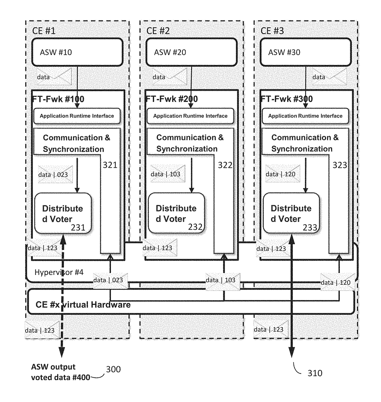
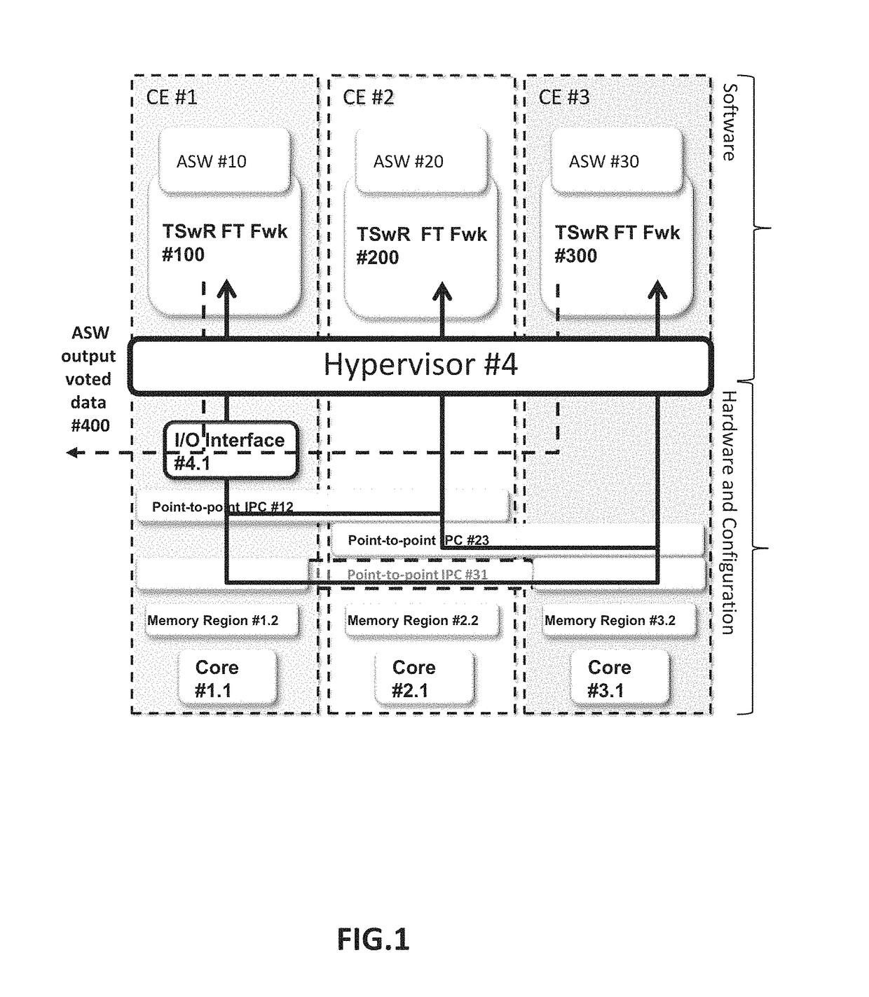
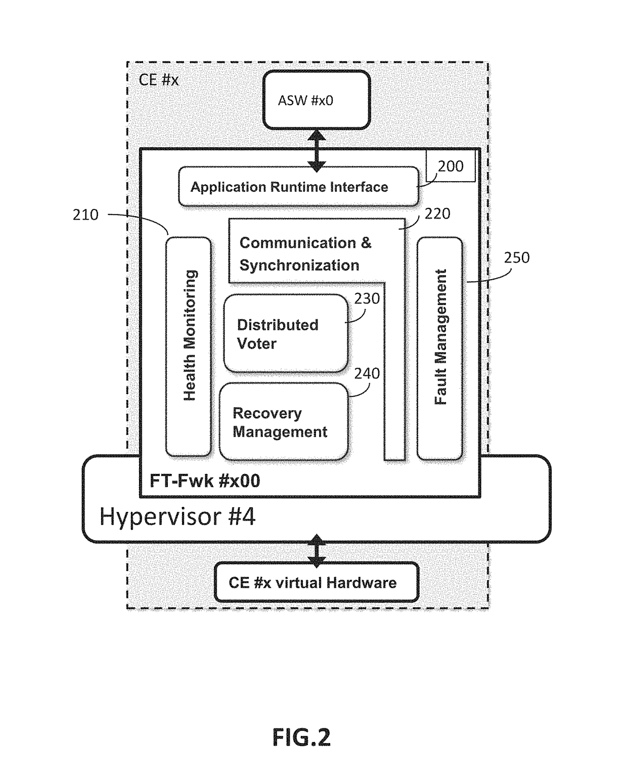
[0053]The following acronyms are used: Commercial Off-The-Shelf (COTS); Single Event Upset (SEU); Single Event Functional Interrupts (SEFI); Triple Modular Redundancy (TMR); Application software (ASW); Computing Elements (CE); Computing Platform (CP); Triple Software Redundancy (TSwR); Fault Tolerant Framework architecture (FT-Fwk); Payload Data Unit (PDU).

[0054]An Single Event Upset (SEU) event corresponds to a change in a state of a bit (an elementary item of information) inside the processor caused by a particle, for example a heavy ion.

[0055]A Single Event Functional Interrupts (SEFI) event corresponds to a locking state of the processor. This event can be a direct consequence of a Single Event Upset (SEU) event which has brought about a change in behaviour of the processor.

[0056]A Computing Platform (CP) is a hardware machine which comprises installed on the COTS multi-core processor, memory units (e.g. RAM-based, EEPROM or PROM) and data input / output (I / O) interfaces (e.g. Eth...


PUM


Abstract

A computer implemented method of detecting a fault in a system comprises the steps of executing at least three virtual machines, each virtual machine executing a same application software, in separated and isolated memory segments and in a dedicated core of a multi-core processor; the virtual machines being synchronized and concurrently executed by a common hypervisor; wherein non-faulty virtual machines provide an identical output message within a predefined time-interval; detecting a fault in an output of a virtual machine, the fault corresponding to a different output message of the faulty virtual machine. Developments include a distributed vote mechanism, pull / push mechanisms, association of output vote messages with a safety extension comprising identification information, virtual machine recovery using data context.

Description

CROSS-REFERENCE TO RELATED APPLICATIONS[0001]This application is a National Stage of International patent application PCT / EP2014 / 076820, filed on Dec. 8, 2014, which claims priority to foreign European patent application No. EP 13290313.9, filed on Dec. 13, 2013, the disclosures of which are incorporated by reference in their entirety.TECHNICAL FIELD[0002]This patent relates to the field of digital data processing and more particularly to the field of fault tolerance systems.BACKGROUND ART[0003]Operating a processor in space, for example in a satellite, is crucial for mission accomplishment and for data integrity. Environmental constraints lead to try to improve the control of systems' tolerance to faults.[0004]Currently, the radiation sensitivity technical problem is mitigated with solutions based on Triple Modular Redundancy (TMR) architectures or / and specific “rad-hard” (i.e. radiations hardened) digital integrated circuits. TMR architectures are well known fault tolerant techniq...

Claims


Application Information

Patent Timeline
Patent Type & Authority Patents(United States)
IPC IPC(8): G06F11/00G06F11/14G06F11/18G06F11/36G06F11/16G06F11/07G06F9/455
CPCG06F11/3612G06F11/1484G06F11/182G06F11/3664G06F11/3672G06F2201/865G06F11/0712G06F11/0757G06F11/1658G06F11/187G06F2201/805G06F9/45533
Inventor DE OLIVEIRA, JAIMEESTAVES, GUYTOURTEAU, FABIANSCHERRER, CHRISTOPH
Owner THALES SA
Why Eureka
Try Eureka