Efficiency submersible thruster

a thruster, high-efficiency technology, applied in underwater equipment, special-purpose vessels, vessel construction, etc., can solve the problems of affecting the influence of windage and friction losses, and the size or weight of the allowable battery, so as to increase the efficiency of the thruster submerged

Active Publication Date: 2018-10-23
WOODS HOLE OCEANOGRAPHIC INSTITUTION
View PDF22 Cites 8 Cited by
  • Summary
  • Abstract
  • Description
  • Claims
  • Application Information

AI Technical Summary

Benefits of technology

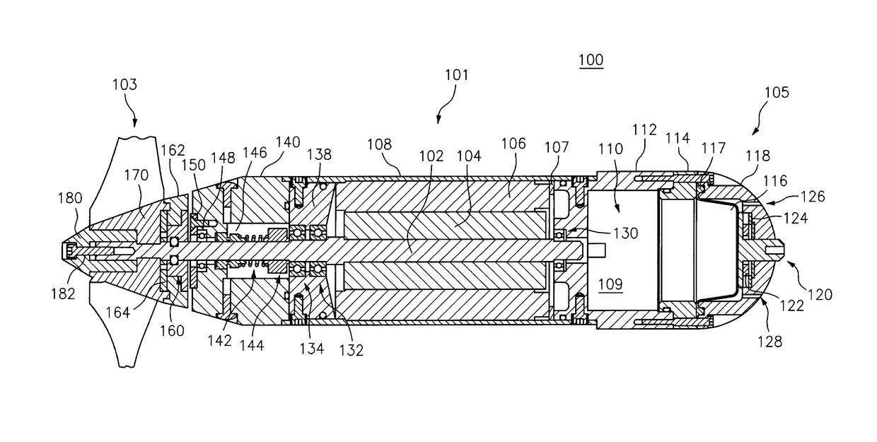
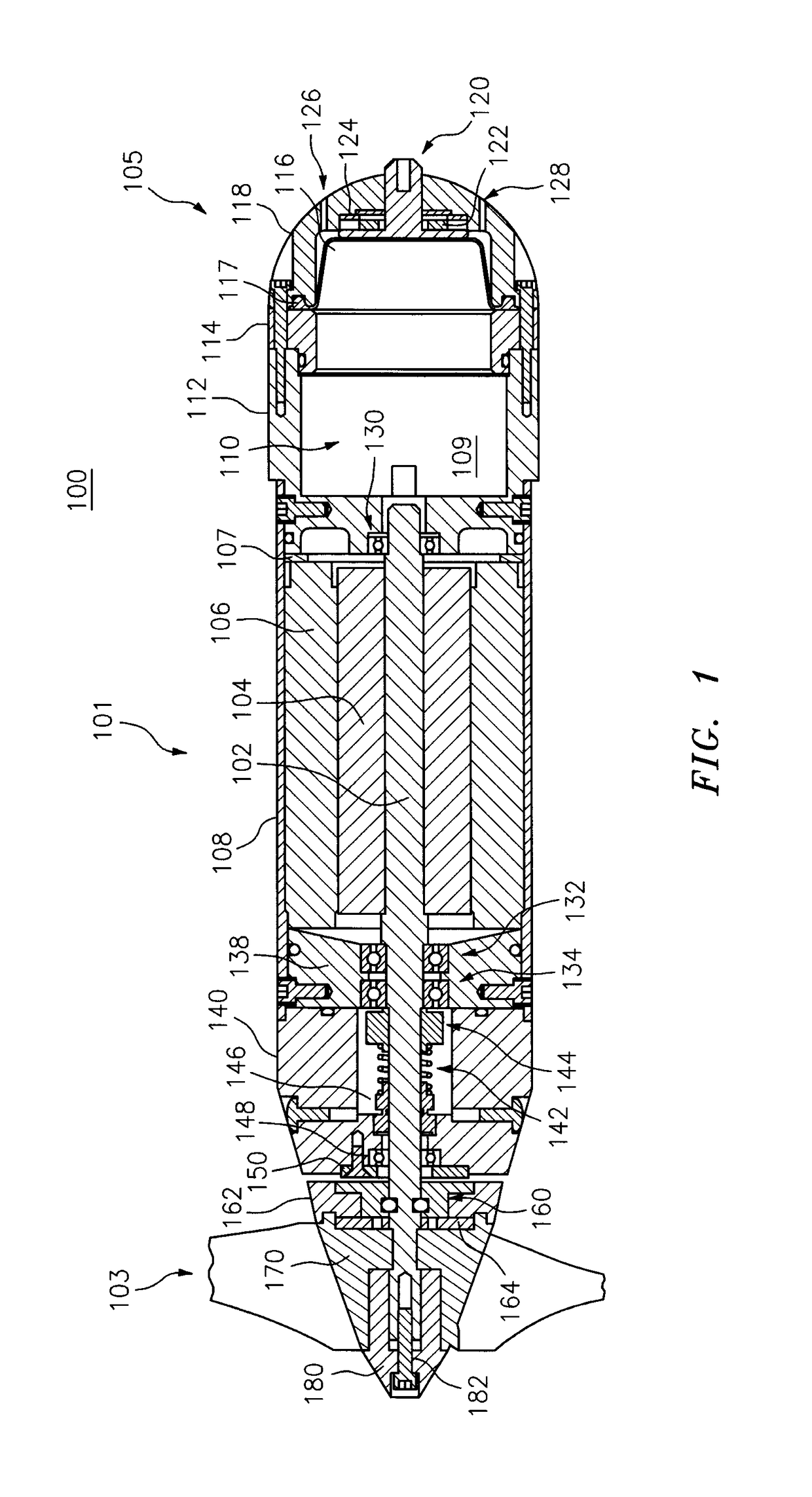
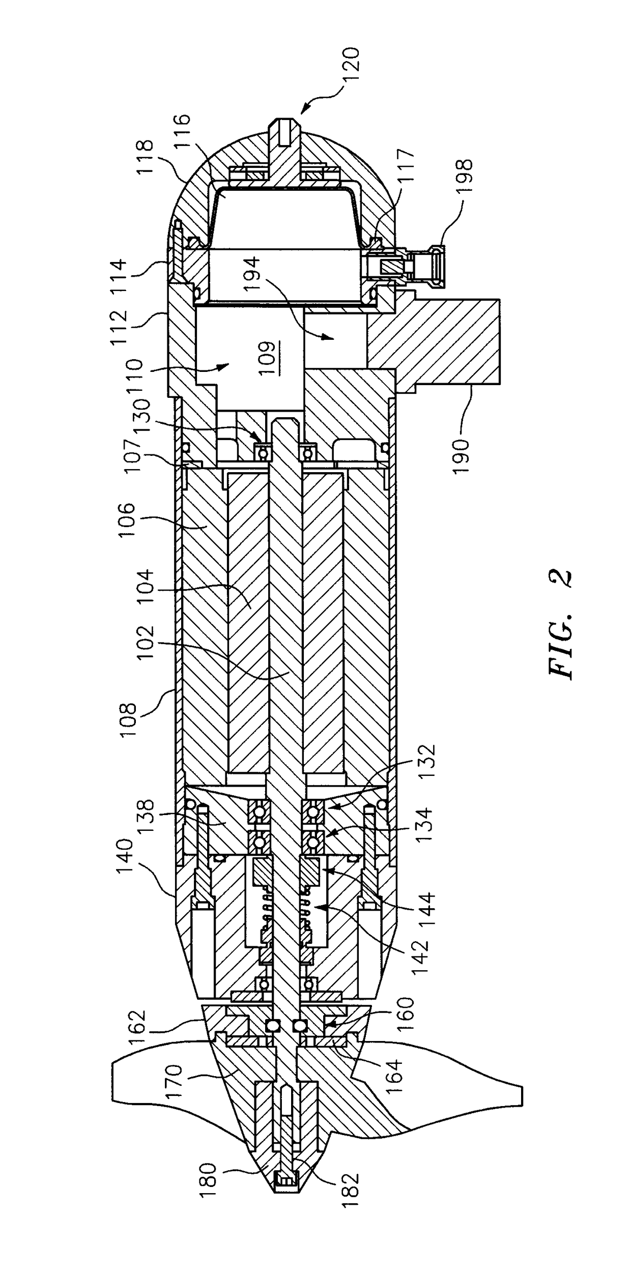
[0017]In some embodiments, the drive shaft is supported by at least three bearings, with at least one bearing supporting the drive shaft in front of the rotor and at least two bearings supporting the drive shaft behind the rotor. In certain embodiments, at least first and second thrust bearings support the drive shaft behind the rotor, wherein each bearing is disposed adjacent to the motor, and the first and second thrust bearings are separated from each other by less than 1 cm. In one embodiment, the bearings are positioned to prevent fore and aft movement of the drive shaft and thereby to reduce efficiency loss. In some embodiments, the pressure-resistant fluid is a non-electrically conductive oil and, in other embodiments, the rotor and the stator include windings, the pressure-resistant fluid is an electrically conductive oil, and the windings include an electrically non-conductive coating.
[0022]This invention further features a method of increasing the efficiency of a thruster submersible in seawater, including selecting a DC electric brushless motor with an efficiency of greater than 75 percent when operated at 250 rpm immersed in a pressure-resistant fluid, the motor having a drive shaft with rotor and a stator matched to the rotor, the rotor and the stator being immersed in the pressure-resistant fluid and being separated by a gap, the motor being disposed in a housing to isolate the pressure-resistant fluid from the seawater, and a rear portion of the drive shaft passing through a Crane seal and a seawater-wetted bearing and extending beyond the housing to drive at least one propeller within the seawater. The method further includes constraining the movement of the drive shaft to a radial and axial play each of less than 0.75 mm for each and reducing the gap between the rotor and matched stator to less than or equal to 1 mm. The motor is operated at less than 50 percent of peak power, wherein said thruster operates at greater than 30 percent end-to-end thrust efficiency.

Problems solved by technology

Thrusters on such are often powered by electric motors, but space and weight capacity may place constraints on allowable battery size or weight.
There are a number of factors which cause losses in efficiency.
Windage and friction losses may dominate power loss in certain constructions.
A too-large gap distance may have a strong negative effect on motor efficiency.
Fixed losses include magnetic core, friction and windage losses.
Friction and windage losses are caused by friction in the bearings of the motor and aerodynamic losses associated with part rotation.
Variable losses include resistance losses in the stator and in the rotor and miscellaneous stray losses.
Stray current losses arise from a variety of sources and are difficult to either measure directly or to calculate, but are generally proportional to the square of the rotor current.
Small diameter brushless motors and gear-boxes may suffer from windage losses if run in oil.
When designed for low pressure operation (1 atmosphere), small-diameter brushless motors and gear-boxes often require heavy housings and magnetic clutches.
Such thrusters are often acoustically noisy and gear-boxes are a source of unreliability.
Disk motors, on the other hand, are only useful when their larger size (disk rotors are generally greater than 6 inches in diameter, especially for higher torque applications) is acceptable, such as in single thruster applications for large diameter torpedo-shaped vehicles.

Method used


Image

  • Efficiency submersible thruster
  • Efficiency submersible thruster
  • Efficiency submersible thruster

Examples


example i

[0074]This Example describes a direct drive thruster for medium endurance, battery powered vehicles such as Autonomous Underwater Vehicles (AUVs), Remotely Operated Vehicles (ROVs) and Hybrid Remotely Operated Vehicles (HROVs). The thruster utilizes a custom wound, brushless DC, frameless motor kit from a commercial motor supplier such as Allied Motion, Inc., as described above. The motor is designed to have a narrow form factor but long length. The computer controlled windings from the kit facilitate a relatively low speed operating point. The motor drives a propeller with high efficiency due to low friction losses, as shown in FIG. 7.

[0075]The Sentry AUV has a depth capability of 5,900 m (19,356 feet), a length of 2.9 m (144″), a height of 1.8 m (71″), a width of 0.8 m (31″) without fins extended, and a width of 2.2 m (88″) with fins extended. A typical weight for Sentry is 1,250 kg (2,750 lbs.). The hydrodynamic shape of Sentry enables fast ascents and descents, especially when p...


PUM


Abstract

A submersible thruster, and methods of optimizing and using same, including selecting a motor with an efficiency of greater than 75 percent when operated at 250 rpm immersed in a pressure-resistant fluid, the motor having a drive shaft with a rotor and a stator matched to the rotor, the rotor and the stator being immersed in the pressure-resistant fluid and being separated by a gap less than or equal to 1 mm. The motor is disposed in a housing to isolate the motor components from a liquid environment. A rear portion of the drive shaft extends through a low-friction shaft seal beyond the housing to drive at least one propeller within the liquid environment. Movement of the drive shaft is constrained to a radial and axial play each of less than 0.75 mm. The method further includes operating the motor at less than 50 percent of peak power, wherein said thruster operates at greater than 30 percent end-to-end thrust efficiency within the liquid environment.

Description

CROSS-REFERENCE TO RELATED APPLICATION[0001]This application is a national phase filing under 35 USC § 371 of international application No. PCT / US2015 / 037548 filed 24 Jun. 2015, which claims priority to U.S. Provisional Application No. 62 / 017,200 filed 25 Jun. 2014. The entire contents of each of the above-mentioned applications are incorporated herein by reference.FIELD OF THE INVENTION[0002]The invention relates to propulsion systems for marine vehicles, more specifically, to high-efficiency electric thrusters for underwater use.BACKGROUND OF THE INVENTION[0003]A marine thruster is a transversal propulsion device built into or mounted on a ship, boat or underwater vehicle. Thruster-based propulsion is relied upon for station keeping, attitude control, and other special propulsion needs. Submersible vehicles such as those used for subsea research and other marine operations may employ one or more thrusters as their principal form of propulsion and maneuverability. Thrusters on such...

Claims


Application Information

Patent Timeline
Patent Type & Authority Patents(United States)
IPC IPC(8): B63G8/08H02K7/14H02K5/22H02K5/173H02K5/132B63H21/17H02K21/12B63B35/00B63G8/00
CPCB63H21/17B63G8/08H02K5/132H02K5/1732H02K5/225H02K21/12H02K7/14B63G2008/004B63B2035/008B63B2702/04B63B2755/00B63G8/16B63G2008/002B63H2025/425
Inventor KAISER, CARLBILLINGS, ANDREW
Owner WOODS HOLE OCEANOGRAPHIC INSTITUTION
Why Eureka
Try Eureka