Apparatus for field-flow fractionation

a technology of apparatus and flow, applied in the direction of measuring devices, scientific instruments, instruments, etc., can solve the problems of increasing assembly size, increasing cost, and using syringe pumps to regulate the flow of slot outlet, so as to increase the measurement sensitivity, reduce the detection limit, and increase the sensitivity

Active Publication Date: 2018-11-20
POSTNOVA ANALYTICS
View PDF32 Cites 1 Cited by
  • Summary
  • Abstract
  • Description
  • Claims
  • Application Information

AI Technical Summary

Benefits of technology

[0022]Removing sample-free solvent from the separation channel during elution leads to concentration of the sample in the remaining solvent, which is led through the first outlet for sample-containing solvent and through the detector(s). This increases measuring sensitivity and at the same time lowers the detection limit.
[0027]Compared with the syringe pumps known from the prior art, the use of a mass flow controller to control the flow rate of the sample-free solvent removed during elution, i.e. to control the Slot Outlet flow, has several advantages: it produces a more compact assembly and does not limit the mounting position, pressure stability can be guaranteed up to 150 bar and controlling is possible depending on the actual flow rate measured. Because of the resulting uniform flow rate control of the sample-free solvent removed during elution with no pressure variations caused by the apparatus, one obtains a detector signal with a better signal-to-noise ratio.

Problems solved by technology

However, using syringe pumps to regulate the slot outlet flow also has disadvantages.
Moreover, two syringe pump units operating in pendulum mode are required for a constant flow volume over a longer period, which increases the size of the assembly and results in higher costs.
Disruption of the laminar flow adversely affects the signal-to-noise ratio and so impairs the detector signal and hence measuring accuracy.
Moreover, as a rule, the syringes used have poor pressure stability and therefore limit the development of systems for high-pressure applications operating at pressures of up to 150 bar.
Poor venting again leads to pulsations which, as already described, impair the laminar flow profile inside the separation channel.
Hence the upright mounting position also limits the potential for developing more compact devices.

Method used


Image

  • Apparatus for field-flow fractionation
  • Apparatus for field-flow fractionation
  • Apparatus for field-flow fractionation

Examples


example

[0137]In a comparative test, the baseline signal of the RI detector of an apparatus of the invention for flow field-flow fractionation was compared with the baseline signal of the RI detector of a flow field-flow fractionation apparatus known from the prior art.

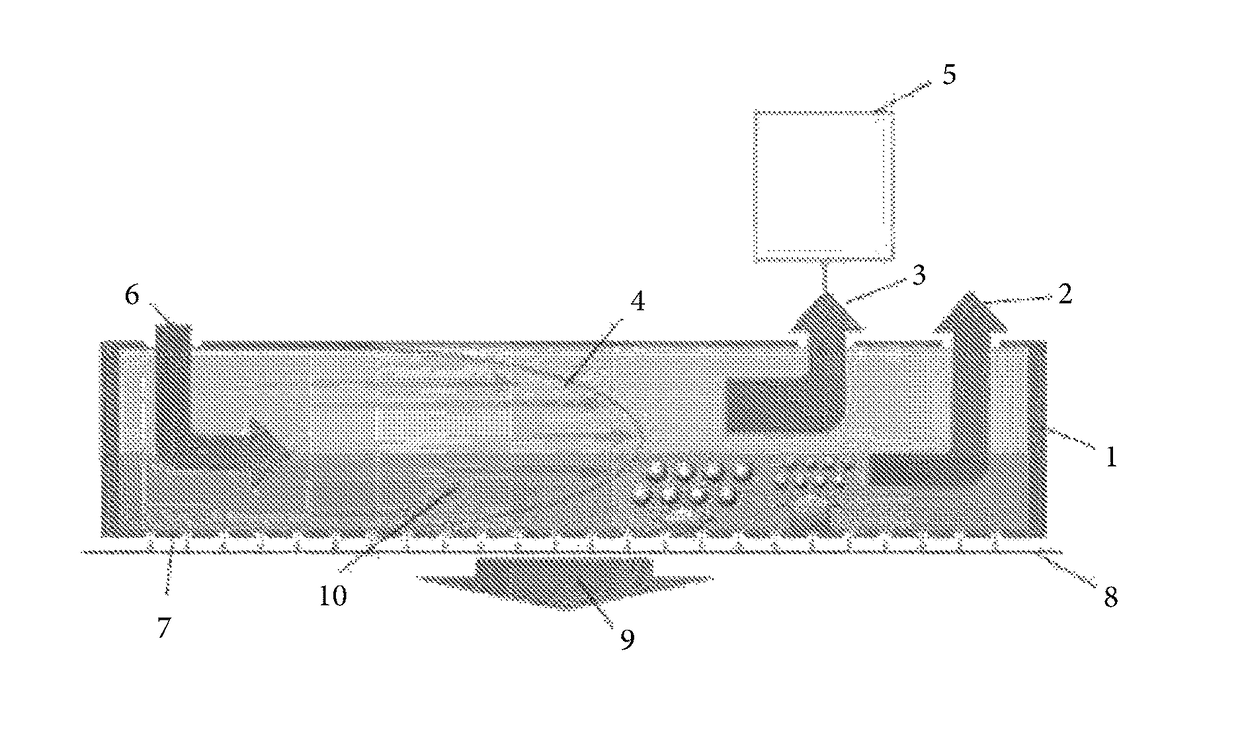
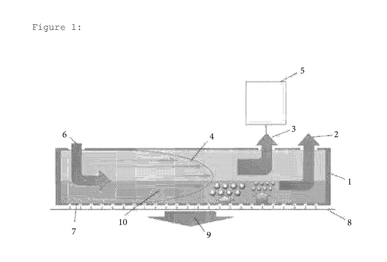
[0138]The measurements were performed with a flow field-flow fractionation system made by Postnova Analytics GmbH Landsberg, Germany. The following settings were used for this.[0139]Separation channel: AF4 separation channel with a cut-off of 10 kDa, comprising a second outlet for sample-free solvent and a syringe pump or a mass flow controller for removing the Slot Outlet flow, said syringe pump or mass flow controller being arranged downstream of said second outlet and connected to it via a capillary[0140]Sample Bovine Serum Albumin (BSA), molecular weight approx. 66 kDa[0141]Cross-flow: 4 ml / min[0142]Flow rate through the detector: 0.3 ml / min[0143]Flow rate through the mass flow controller: 0.7 ml / min[0144]Detector: RI det...


PUM

PropertyMeasurementUnit
pressuresaaaaaaaaaa
sizeaaaaaaaaaa
molecular weightaaaaaaaaaa

Abstract

The present invention relates to an apparatus for field-flow fractionation and to a method for separating samples by means of field-flow fractionation using this apparatus. The apparatuses of the invention comprise a separation channel which, in addition to a first outlet for sample-containing solvent, comprises a second outlet for sample-free solvent, wherein the second outlet is arranged in a region of the separation channel from which sample-free solvent may be removed during elution and a flow volume control device is arranged downstream of the second outlet. They are characterized in that the flow volume control device is a mass flow controller.

Description

TECHNICAL FIELD[0001]The present invention relates to an apparatus for field-flow fractionation and to a method for separating samples by means of field-flow fractionation using this apparatus.PRIOR ART[0002]Field-flow fractionation (FFF) is a quasi-chromatographic method of analysis for separating macromolecular and colloidal samples. In contrast to chromatography, sample separation in field-flow fractionation does not take place in a packed column, but in an open separation channel which does not contain a stationary phase.[0003]Owing to the low height of the separation channel, a laminar flow with a parabolic flow profile is formed within the separation channel. Separation of the samples is carried out by a force or separation field which is applied vertically to this flow within the separation channel. Under the influence of the applied separation field and the counter-acting diffusion of the sample particles, the individual components of the sample are separated. First, a state...

Claims


Application Information

Patent Timeline
Patent Type & Authority Patents(United States)
IPC IPC(8): G01N30/00B01D11/04G01N30/74
CPCG01N30/0005B01D11/04G01N30/74G01N2030/003G01N30/32
Inventor WELZ, ROLANDKLEIN, THORSTEN
Owner POSTNOVA ANALYTICS
Why Eureka
Try Eureka