
Grounding structure and grounding method of vacuum tube audio amplifier

a vacuum tube audio amplifier and grounding technology, applied in the field of audio amplifiers, can solve the problems of aggravated humming, leakage of a conventional vacuum tube audio amplifier, and large volume of the amplifier, so as to effectively address the problem of hum, avoid leakage, and reduce the residual noise of the vacuum tube audio amplifier

Active Publication Date: 2018-11-20
ECHOWELL ELECTRONICS
View PDF2 Cites 2 Cited by
  • Summary
  • Abstract
  • Description
  • Claims
  • Application Information

AI Technical Summary

Benefits of technology

The present invention is about a new grounding structure and method for a vacuum tube audio amplifier that solves the problem of hum. By eliminating a grounding metal bottom plate, the amplifier is made more compact and less prone to leakage. This allows for a smaller and lighter vacuum tube audio amplifier to be created. Overall, this invention allows for a more efficient and effective vacuum tube audio amplifier that is easy to use and compact.

Problems solved by technology

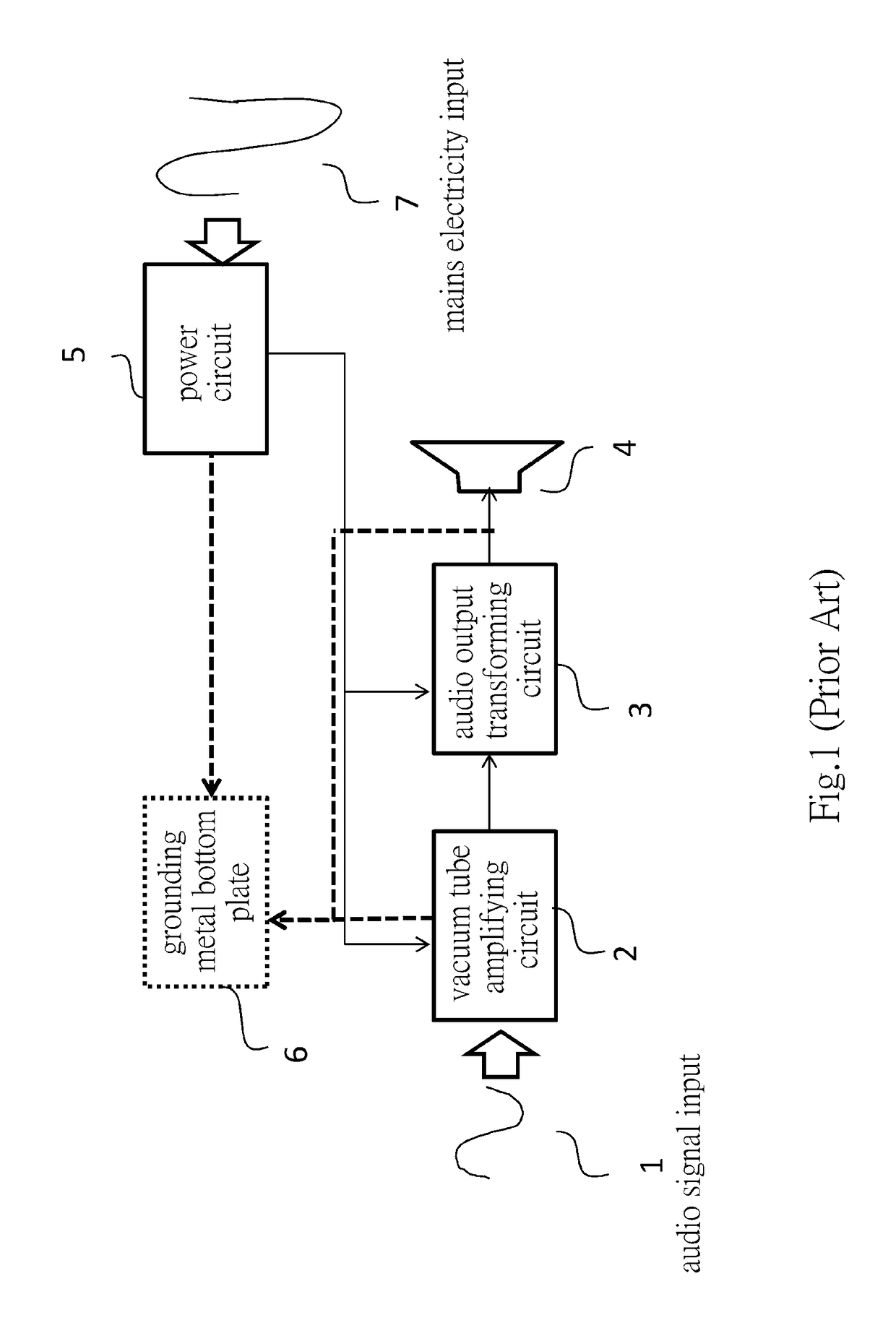
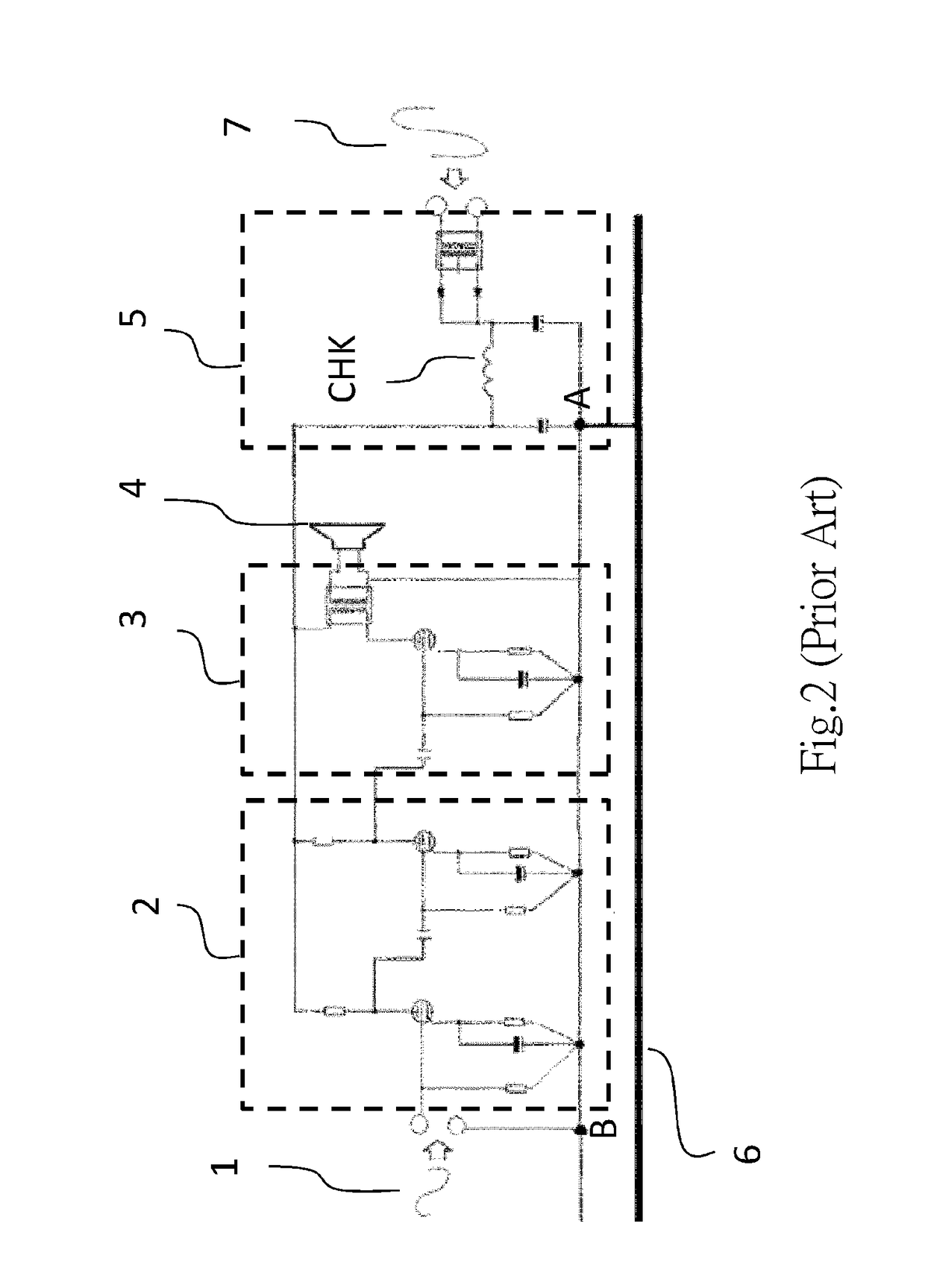
However, even though the grounding metal bottom plate 6 of a conventional vacuum tube audio amplifier may provide grounding shield, it cannot eliminate the residual AC noise and impulse noise, resulting in that the user could hear clearly the residual hum and impulse hum in the sound played by the loudspeaker 4 at a short distance (within about a meter).
Also, the choke in the power circuit 5 would be coupled with high-frequency noise and further aggravate the problem of humming.
Moreover, the grounding metal bottom plate 6 results in huge volume of the amplifier and expensive cost, and as the grounding metal bottom plate 6 is mostly designed integrally with the casing, which further leads to leakage in a conventional vacuum tube audio amplifier.
Even though the conventional vacuum tube audio amplifier has superior sound quality, due to bulky volume and the problem of humming within a short distance, a desktop model cannot be developed nor do such vacuum tube audio amplifiers fit in ordinary households.

Method used


Image

  • Grounding structure and grounding method of vacuum tube audio amplifier
  • Grounding structure and grounding method of vacuum tube audio amplifier
  • Grounding structure and grounding method of vacuum tube audio amplifier

Examples


Embodiment Construction

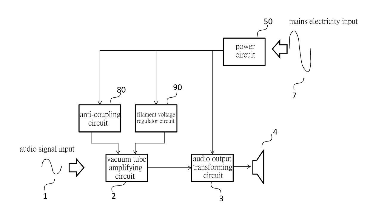
[0022]The present invention provides a grounding structure and method of a vacuum tube audio amplifier, with a view to realizing a lightweight desktop model of the vacuum tube audio amplifier. With respect to power source, the grounding structure and method of the vacuum tube audio amplifier include utilizing a power circuit without a choke, an anti-coupling circuit and a filament voltage regulator circuit to lower the residual noise of the vacuum tube audio amplifier so as to effectively reduce the hum. With respect to grounding, the grounding structure and method of the vacuum tube audio amplifier utilize the negative output terminal of the audio output transforming circuit or the negative terminal of the filter capacitor in the power circuit as the single ground terminal, and a grounding metal bottom plate is not arranged in the vacuum tube audio amplifier in order to reduce noise, prevent power leakage, and thereby achieve a compact body for a vacuum tube audio amplifier.

[0023]F...


PUM


Abstract

The invention provides a grounding structure and a grounding method for a vacuum tube audio amplifier, the grounding structure and the grounding method including: with respect to a power source, utilizing a power circuit without a choke, an anti-coupling circuit, and a filament voltage regulator circuit; and with respect to the grounding method, utilizing an negative output terminal of an audio output transforming circuit or a negative terminal of a filter capacitor in the power circuit as a single ground terminal of the vacuum tube audio amplifier, and not arranging a grounding metal bottom plate therein, in order to achieve a compact, lightweight desktop model of a vacuum tube audio amplifier.

Description

BACKGROUND OF THE INVENTIONField of the Invention[0001]The present invention relates to an audio amplifier and more particularly to a light-weight vacuum tube audio amplifier.Description of the Prior Art[0002]Vacuum tubes have excellent linear output characteristics, so a conventional vacuum tube audio amplifier that uses vacuum tubes for processing audio signals can provide superior sound quality. See the circuit structure of a conventional vacuum tube audio amplifier as exemplified in FIG. 1. A conventional vacuum tube audio amplifier receives an audio signal input 1 and then outputs the signal to a loudspeaker 4. Moreover, the conventional vacuum tube audio amplifier includes a power circuit 5, a vacuum tube amplifying circuit 2, an audio output transforming circuit 3, and a grounding metal bottom plate 6, wherein the power circuit 5 is utilized to receive a mains electricity input 7 and provide power to the vacuum tube amplifying circuit 2 and the audio output transforming circu...

Claims


Application Information

Patent Timeline
Patent Type & Authority Patents(United States)
IPC IPC(8): H03F1/02H03F1/28H03F3/181
CPCH03F1/28H03F3/181H03F1/0216H03F2200/03H03F2200/541H03F1/54H03F3/22H03F1/04H03F1/20H03F1/30H03F2200/186H03F2200/459H03F3/40H03F3/45
Inventor CHEN, HSI-HSIEN
Owner ECHOWELL ELECTRONICS
Learn More